This discussion has been locked.
You can no longer post new replies to this discussion. If you have a question you can start a new discussion

Six phase electric supply.

db3fecfec837110019a09ec7585f1e33-huge-a72a8449-52a6-4c2f-b7dd-13b18ecd4933.jpg


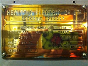
This photo has appeared on my Facebook page.


I will let this run a bit then tell you where it is and who posted if if no one guesses, though I suspect at least one forum member will recognise it straightaway.


If I read it correctly it does say it has a six phase supply.


Andy Betteridge
  • https://www2.theiet.org/forums/forum/messageview.cfm?catid=205&threadid=53714
  • Hmm,

    I suppose Manx is famous for three legs therefore three phase becomes six
  • This is the rating plate from a mercury arc rectifier set, 200 kW means that it is one of the larger rectifier sets made by The Hewittic Company, probably two or more rectifiers in parallel.  As it refers to 6-phase, it may be the rating plate from the transformer.  Mercury arc rectifiers were one of the few ways that ac supplies could be converted to dc at high power level in the earlier part of the 20th century when solid state rectifiers could not handle high powers, and remained in use into the 2000's, notably on the South to North island dc link in New Zealand, and on the Manx Tramway until a few years ago.

    The six phases are derived from 3-phase, a delta wound primary with two star connected secondaries, one in anti-phase to the other.  By connecting the star points together, six phases are obtained. 


    I look after a working set on public display at the Kempton Steam Museum.


    David
  • The modern way to make 6 phases, for a 12 diode rectifier, is to have one 3phase transformer core and primary, and 2 sets of 3 secondary windings, one secondary configured as a delta, and the other 3 configured as a star, with the no's  of turns in the right ratio to give the same p-p voltage on all 6 lines - the advantage is that the DC that is produced by rectifying this with  12 diode bridge is almost ripple free, even without any smoothing capacitance, and when loaded  the primary side currents are not dominated by 3rd harmonics, and has a very good power factor compared to a simple rectifier.

    The technique dates back to the late 1800s, and DC for traction current for trains and trams was often derived this way.

    670V may be ex  London underground.

    I thought Kempton Park was 200-250V, is that recollection wrong  ?


    It is still done today though the diodes are now chunks of silicon (or at least several in series to withstand the reverse voltages ), to derive DC supplies for large valve based broadcast transmitters.
  • Mike, you are right, Kempton Park rectifiers give 200 v dc at 200 amps.


    To reduce the 3rd harmonic primary currents the two star points are connected via a centre tapped auto transformer, the neutral taken from the centre tap.  This has the effect of "flattening" the peaks and increasing the conduction time of each anode, and also reducing the ripple.


    David
  • Link to the Old Laxey Manx Electric Railway substation Facebook page.


     Andy Betteridge
  • I'm glad that the Manx rectifiers are to be preserved.  I was in contact with them in 2012 when they had a problem with the Groudle sub station.  It transpired that one of the rectifiers had been destroyed with loss of vacuum probably as a result of a lightning strike.  I think it was at that point it was decided to complete the replacement with solid state rectifiers.


    David
  • The rating plate is indeed from one of the ex Glen Road rectifiers. The transformers have a strange arrangement - it is a “centre-tapped star” arrangement, with the star point formed at the centre of the windings, giving a six phase output. For those that want to see the rectifier running, there is a short clip of it here: https://www.youtube.com/watch?v=yjMZ5qtyCUc&fbclid=IwAR0VkeNWzioV6VcuyzfoZb4VBGB_ryjTIgh5zcznhD3dmPaBSW_cYNJc1pg. Most of the noise is from the cooling fan in the base of the cabinet, which is just visible. It’s speed increased as the rectifier current increased. 


    Regards,


    Alan.