This discussion has been locked.
You can no longer post new replies to this discussion. If you have a question you can start a new discussion

Cattle deaths

Some 10 prize bullocks died in quick succession whilst housed over winter in a cattle shed. The government vet was unable to reach a conclusion on cause but apparently does not discount electric shock as an indirect cause. 

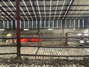
The shed comprises steel columns and trusses with corrugated iron sheeting over. The floor comprises re-Inforced concrete slats over the slurry tank. The pens have steel barriers supported by steel posts all of which are heavily corroded but still making contact with other albeit fortuitously.

The earthing system is TT with the shed steelwork on its own providing a substantially low impedance of 5 ohms using a loop tester. A 100mA RCD protects the rather ropey lighting circuits.defccf32df3c757507a0db6ad0a35f87-huge-a5af3537-8eae-4a3c-9126-68fa60b61ac7.jpg

whilst the floor could be wet, I can’t conceive how a voltage difference could be established even if the steelwork was at 230v


  • mapj1:
    The same workers measured electrical resistance of dairy cows and determined an average value 390 ohms. Based on this work, it would appear that dairy cattle can "sense" currents of 1.0 to 6.0 ma AC and demonstrate a mild avoidance reaction at these levels. Using a 390 ohms resistance value, this translates to a threshold sensitivity of 0.4 to 2.4 volts.


    That's getting closer to my question as to how much electricity does it take to fell an ox.


    390 Ω is a good bit less than a person (even without wellies) which isn't surprising given the greater CSA, so it appears that they are more sensitive to electricity than we are.

  • There used to be dire warnings about using the TT installation electrode as an electric fence earth electrode, the danger being that a fault on the installation raising the voltage on the electrode could lift the voltage on the fence to lethal levels.


    Andy Betteridge
  • A team from the DNO were on site yesterday. I was there as well but little in the way of communication between us as I imagine they realise that litigation is likely. Nonetheless the engineer did say that all was sound on their side with both the HV and LV earths falling well within their 40/20 ohm requirement. In fact the LV earth was recorded at just under 12 ohms. Not sure how the measurements were taken but my loop impedance test on the shed steelwork with all other earths disconnected was just below 5ohms. The shed in question is quite some distance away.
  • I wonder if the DNO are sure there is no underground cable fault present ?


    I think a long lead and a voltmeter testing between the supply earth and and exposed and extraneous parts would be a useful exercise kitted out with rubber boots for PPE. The and between exposed and extraneous  parts. Followed by the Capon test between a long screwdriver stuck in the ground and exposed and extraneous conductive parts.
  • you may find a garden fork and a croc clip makes a better temporary earth, especially if like me your longer screwdrivers are insulated.  Expact a Ze of 50-500 ohms from the garden fork in full depth.

    For contact onto concrete, tarmac or other 'hard' surfaces a contact can be made with a salt water soaked old towel or similar and a bundle of bare wire or a stainless steel pan scrubber pressed into service if you only need to pick up enough to make a volt meter indicate (no good as a real safety of life earth of course but OK for finding voltages over a 'footprint' sort of area.)

    Ze in such a case is a bit nebulous but is a representative  measurement phantom for the situation of a sweaty bare-foot contact, and much more convenient and humane than using a real persons foot.

    Be aware that you will see some  DC anyway, as the saltwater and the electrodes form a crude battery, and both ends are most unlikely to be identical voltages. voltages at 50Hz AC however, should be considered as more real, though if it all vanishes when any current is drawn, it is not serious. If however you can get mA to flow then investigation is needed.

  • When I said about knocking up a wooden frame with some nails in it to replicate the likely span between the cattle’s feet I was forgetting about the nose and tongue, it would actually need five nails positioned accordingly.

    The diagram in this article suggests there can be the full voltage gradient 230 volts to zero across a cow on soil.


     Andy Betteridge
  • Former Community Member
    0 Former Community Member

    lyledunn:

    Some 10 prize bullocks died in quick succession whilst housed over winter in a cattle shed


    Hi Lyle, how quick do you mean by quick? Within minutes, hours or days etc, and were they randomly fallen in the shed or in a particular spot?


  • Sparkingchip:

    ...

    The diagram in this article suggests there can be the full voltage gradient 230 volts to zero across a cow on soil.


    The figure is rather simplified but is about right for a rod of say 1m to 1.5m length - half the voltage drop is in a circle of radius more or less equal to the rod length (all sorts of assumptions about uniform soil density and no wet or dry  patches or buried rocks are hidden- in reality the voltage contours are far from perfect circles.) also the circles are closer near the electrode and wider spaced further out, if you want each contour to be the same no of volts from each neighbour.


    Fence off a couple of rod lengths around the electrode for best results. Also for pets or small children, worth insulating the top foot or so, so that even if they get on the soil at the surface right near the centre there is at least some resistance in series

  • In the original post Lyle said “I can’t conceive how a voltage difference could be established even if the steelwork was at 230v”.


    If the roof has steel trusses siting on steel stanchions, but timber purlins between them presumably they could have a voltage difference between them.


    The steel slats of the floor are sitting on concrete sleeper walls and presumably could have a voltage difference within the span of a bullock.


    The first impression from looking at the photo is there lots of interconnected steel work, but actually it’s probably not as connected as it may appear.


    There has not been any mention of were the lighting is mounted or what other circuits there are, if any.


    I think it’s probably okay to assume there could be a voltage difference from the stanchions yo the floor and across the floor, without doing much testing.


    Given the low earth reading of 5 ohms if there is a fault it has livened up something that is not bonded on either on purpose or gratuitously and is not serving as an earth electrode itself, as tends to be assumed with a stanchion or something bolted to one.


    I would knock off the main switch, interconnect the live and neutral in the distribution board then connect a long wander lead to the live and neutral in the DB and an insulation tester to the other end of the wander lead; then I would start by doing an insulation test to every stanchion, every other bit of metal work in the roof frame then run the tester across the steel floor.


    I would make up or buy a long pole to test the roof, rather than trying to do it off a ladder.


    Then a cable running over a steel truss that has been damaged may be found or something similar.


    Andy Betteridge 


  • Former Community Member
    0 Former Community Member
    Before Mr Betteridge gets too excited, electrocution amongst cattle is rare especially those numbers, the most common cause of cattle deaths is one of the Clostridial diseases, most of them tend to be rapid and fatal, Clostridia is part of a family of anaerobic bacteria found in the soil and farm environments, grass, hay and water, it does take a while to spot as cultures have to be developed to identify the particular strain, just an observation.


    Rob.