This discussion has been locked.
You can no longer post new replies to this discussion. If you have a question you can start a new discussion

Generator earthing

Hi


I have a tractor driven Backup generator to install on a farm shortly and have a query regarding the earth spike. Does it need to go directly back to the MET or can I connect it directly into the generator earth terminal, the latter being Quite a lot simpler   In my case? 


thanks

  • Almost right. Generator > 10 metres or so of cable( yet do be decided which type of cable) > mccb/rcd in switchboard > changeover switch. Yes there is no short circuit protection or earth fault protection to this cable, overload protection being provided by the downstream mccb
  • As above, you might not need short-circuit protection if the generator itself solves the disconnection problem - but if you can't rely on that, then 434.2.1 would normally limit the length of conductors without fault protection to 3m (in addition installing in a manner to reducing the risk of faults and fire and danger to persons to a minimum).


    Oddly when you consider L-PE faults and protecting against electric shock, you can adopt double/reinforced insulation or equivalent for any length of conductor - so it seems a bit inconsistent not to have an equivalent option for short circuits.


    434.3 (i) does provide another exception for generators, between the generator and its 'associated control panel' without an apparent limitation on length (with similar demands for reducing the risk of faults and fire and danger to persons to a minimum) - but is the switchboard really the generator's control panel?


    If you've got a separate MCCB/RCD for the generator anyway, it is really a lot more effort to re-locate into its own enclosure closer to the generator?


       - Andy.
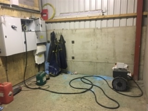
  • ac2edb00fc882300a89ce96e725f3634-huge-52b6acb4-3519-4f86-ba0f-d3b5a9c29185.jpg
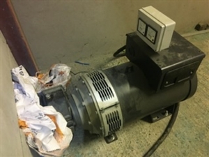
    6eb8a59504b8268a8ffca66ca8b133cc-huge-5d55c3a9-c2ce-41a6-aee4-25f17f620d76.jpg

    Hi Andy


    I was onsite today on an unrelated matter so took the opportunity to take a couple of photos to better explain. Excuse the cable already connected, this was for testing purposes. The more I consider it, I think for peace of mind I will do as you and others Have suggested. I will remove the mccb/rcd from the switchboard and mount it in a separate enclosure adjacent to the generator. There will then only be a short length of cable from the alternator to new enclosure and then I will use swa from here to switchboard terminating directly to the changeover switch, the swa being adequately protected. Thanks for your opinion on this
  • Hugh

    Did you say that alternator is 60 kVA, because I think not! What exactly does the rating plate say? It and the gearbox are rather too small for 100HP. As your cable is only a few metres you don't need to do anything, just make sure it is SWA along the wall and installed properly, there is no risk of failure. What is the ammeter maximum, the photo is too defocussed to read it?
  • Hi


    its actually 80kva according to the plate on it. Sorry about the picture quality. All the same for my own peace of mind I think I’ll have my mccb/rcd adjacent to the alternator as described earlier
  • There a no ammeter on the set, only a voltmeter and frequency meter
  • That cable trailing off to the cabinet with the front cover missing looks like the sort of thing that passes for a neat final installation in some quarters.  ' final connector M6 wing nut...' ?

    Using the overalls for scale it looks quite a compact unit - is it perhaps a only 80kVA with some time limit, like 10mins on 10 mins off, and more like half that rating continuous ? 

    The units for welding are rated rather like that, and look similarly small for the rating.

    You could always add an ammeter   in your new box by the genset or on the wall if you felt the need.

  • davezawadi (David Stone):

    Hugh

    Did you say that alternator is 60 kVA, because I think not!


    That was my thought - it doesn't look big enough. However, it is difficult to get a good idea of scale from those photographs. As far as I can see from examples on line, the casing would be around 3 ft in diameter and that one looks smaller; but I don't doubt what Baldyhugh says.


    If the alternator is connected by SWA all neatly cleated to the floor and wall, is there any realistic chance of a fault or short? If there were one, would those fixing bolts withstand the force?


  • Former Community Member
    0 Former Community Member
    If the alternator is connected by SWA all neatly cleated to the floor and wall, is there any realistic chance of a fault or short?


    Somewhere I recall that the use of SWA doesn't meet the requirements of 434.2.1 as SWA isn't deemed to be installing in a manner to reducing the risk of faults and fire and danger to persons to a minimum. This could be from a GN or even dare it, a "best practice guide" type of publication?


    My understanding is that the proximity of the cores to each other and their insulation between each other and the armouring can be bettered by other methods of installation and so doesn't meet the minimum option.


    More often SWA is "incorrectly" used to provide an extension to an existing bus-bar chamber to another adjacent one when more "ways" are required.


    Regards


    BOD
  • Former Community Member
    0 Former Community Member
    its actually 80kva according to the plate on it.


    No good trying to run it from the grey Fergie then! Or the retired yard scraper once it's cleaned to find the PTO!


    80 kVA, you're looking at around 120 bhp at the PTO which takes it over the standard 540 PTO usage and into the larger splined 1000 PTO.


    Most farmers don't realise how much fuel they'll need to keep the set running................. Most think it'll be cheaper on "red" than through the meter!


    And fatalities or life changing injuries are still happening from PTO misuse unfortunately.


    Regards


    BOD