This discussion has been locked.
You can no longer post new replies to this discussion. If you have a question you can start a new discussion

PC Monitors switching off and DVI to HDMI cables failing

Former Community Member
Hi,


I'm new to the Forum but i'll try and explain this as best I can as it's a strange one!.. Sorry it's a long one!


The issue -

For several weeks now, there have been reports of multiple Monitors intermittently switching off and on again across 5 or 6 different PC users in an office of 20 PC users. Sometimes as little as twice a day but up to as often as15 times a day Apparently, this has led to multiple monitor leads no longer working and being replaced but the issue still remains.
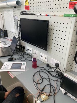

The system -

Sub DB fed from Main DB on a TNCS system (The office is part of a larger factory / workshop set up). The circuit in question is a 32A Ring with a 30mA RCD up front, feeding 24 twin sockets in 4.0mm2 T+E. It is dedicated to office use only. Only 1 of the 2 earth connection points have been used on each socket outlet and no extra earth has been ran alongside it, so simply a ring main earth and that's it. It is a fairly new installation but the equipment has all been used before as the personnel have just moved all their stuff from an old office into a new one. There is an identical ring circuit feeding the other side of the room with the same set up but with no issues with their monitors reported (same monitors and fed from the same Board).

For the most part, monitors and PC's are plugged directly into the wall sockets but there are a few stations that are fed from 4 way extension leads. Problems are occurring on both set ups.


What's been tried / observed already -

Socket fronts dropped off, no N/E reversals and all connections tight. R1R2 = 0.05 ohms and insulation resistance test at the board = >999 Mohms so no issues across any combination of conductors.

Mis-leading -

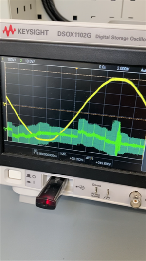
I had a cheap and cheerful meter connected via Bluetooth that was sampling and logging every second, that picked up frequency spikes of up to 350Hz! I am now convinced that this is a banana skin and that the meter may have been suffering some communication interference (maybe caused by the same fault dropping the monitors out?!) as I later connected an Oscilloscope which did not show any fluctuation on 50 Hz. Thought i'd mention though just in case!


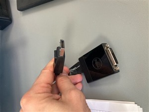
What the scope did pick up though, was a voltage on the exposed metal casing at the bottom of the monitor at the rear (Where the DVI ports etc are) that spiked whenever the monitor was turned off via the fault.


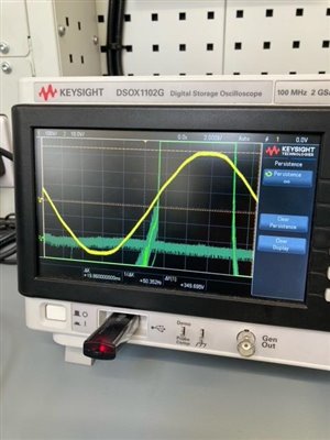
Here's where it gets weird.... The PC users, prior to my involvement had set up a 100w lamp (Bayonet type) to see if it would flicker when the monitors turned off (which is doesn't) but in actual fact, when you turn the lamp on and off, it would throw huge spikes onto this metal casing at the back of the monitor! I measured up to 100V on the scope! It would also turn the monitor OFF/ON. The lamp has no earth connection as it is all plastic housing.

When I plugged the lamp into the sockets on the other side of the room (Separate ring circuit) it did make a slight reading on the scope when probing the same part of somebody else's monitor but nothing like the amplitude I was getting on the problem circuit. More like 5V rather than 100V and no monitor issues either.

I can only assume that the RCD isn't tripping because it is such a fast spike! However that does surprise me that it would still damage a lead!?

I have turned off some of the Aircon unit circuits for as long as i've been able to as I wondered if a faulty inverter may be throwing something down the earth but it didn't seem to reduce the flickering.


So yeah.... Help!
  • Former Community Member
    0 Former Community Member
    84a6d69dcb41ee3a520de97ab6874a04-original-13.jpg
  • Interesting results of the swap test. So, the spikes are not coming in down the main supply. Pity, as catching them at that point would have been easy.


    So either (1) !the problem is conducted but not via the incoming mains or (2)radiated and received.


    1) There is a spike generator plugged into ring 2, and that could be one icky lead, one loose terminal in a socket, an arcing switch or something inside a PC or monitor,


    2) The spikes are picked up by the leads and wiring layout acting as an unlucky pick-up antenna, and something else, either electrostatic, or switched loads on another circuit some distance away is 'illuminating' this,  in just the right way and the right sort of attack waveform to make the large voltages pile up in the wrong places.


    I presume there is nothing special about the dirty ring - it is a ring and all 3 cores follow the same route no great loops where N and L diverge or spurs to feed something next door.....


    If you wanted this to happen to order it would be really quite hard to arrange. I feel your pain, this sort of thing can be right sod to identify, even more so with limited access.

    I do not really have more to suggest I'm  afraid, but others may, and in any case keep us posted.

    Mike.

  • Former Community Member
    0 Former Community Member
    mapj1:

    Interesting results of the swap test. So, the spikes are not coming in down the main supply. Pity, as catching them at that point would have been easy.


    So either (1) !the problem is conducted but not via the incoming mains or (2)radiated and received.


    1) There is a spike generator plugged into ring 2, and that could be one icky lead, one loose terminal in a socket, an arcing switch or something inside a PC or monitor,


    2) The spikes are picked up by the leads and wiring layout acting as an unlucky pick-up antenna, and something else, either electrostatic, or switched loads on another circuit some distance away is 'illuminating' this,  in just the right way and the right sort of attack waveform to make the large voltages pile up in the wrong places.


    I presume there is nothing special about the dirty ring - it is a ring and all 3 cores follow the same route no great loops where N and L diverge or spurs to feed something next door.....


    If you wanted this to happen to order it would be really quite hard to arrange. I feel your pain, this sort of thing can be right sod to identify, even more so with limited access.

    I do not really have more to suggest I'm  afraid, but others may, and in any case keep us posted.

    Mike.


    I'm thinking it's 2) to be honest. Once these patch leads arrive i'm really hoping it will at least mask the problem.


    The ring is so straight forward and the Spark that installed it is a really decent sparks that they use all the time. The only difference is that it looks like the dirty ring is wired in 4.0mm2 as it's stranded and the other ring is solid strand 2.5mm2 which may or may not have had an influence regarding electron flow around the outer surface, more surface area and all that jazz but who knows... not me that's for sure! haha!


    I just stuck the scope on a little one man station on the other side of the wall in a different room and on a different phase that's using a laptop plugged in via a HDMI lead to a small monitor and let's just say I wish I hadn't as I really do not understand what I saw there! ? Measuring the outer of the HDMI lead whilst plugged in to the laptop but with the monitor switched off and it was all over the place!! Shame I can't show a video but i'm definitely going to stop looking at the scope now as suggested as it's causing more confusion than anything else!...... I'll keep you posted next week if I make any progress and thanks to all that have tried to understand my ramblings!


  • Out of interest I connected my scope to the 7.2v winding of a heater transformer and then plugged in a table lamp borrowed from the house switching the lamp on and off with its own switch made a few flicks on the mains waveform they were too fast to see properly. However turning the socket switch on and off as slowly as I could produced similar traces to the OPS ie noticeable fuzz on the positive and negative crests of the mains wave assuming im understanding it correctly I was producing spikes of 5 to 10 volts over the peak mains volts all this from a humble light bulb the RFI was clearly audible on my radio in the same room tuned to 648 kilocycles although I'm sure the noise would of been all over the place
  • Former Community Member
    0 Former Community Member
    Kelly Marie Angel:

    Out of interest I connected my scope to the 7.2v winding of a heater transformer and then plugged in a table lamp borrowed from the house switching the lamp on and off with its own switch made a few flicks on the mains waveform they were too fast to see properly. However turning the socket switch on and off as slowly as I could produced similar traces to the OPS ie noticeable fuzz on the positive and negative crests of the mains wave assuming im understanding it correctly I was producing spikes of 5 to 10 volts over the peak mains volts all this from a humble light bulb the RFI was clearly audible on my radio in the same room tuned to 648 kilocycles although I'm sure the noise would of been all over the place


    That's interesting! I'm guessing you'll see all kinds of weird and wonderful anomalies through the scope. It's the significantly higher amplitudes of the distortions that interested me between the "dirty" ring and the better one but like I say, I think i've gone as far as my understanding will take me regarding scope readings but just purely out of interest and because sharing is caring i'll stick some pics on of that little setup I mentioned on Friday and show you the scope readings.


    This is just a little one man station on a separate circuit (L3) next door. It's a 1M HDMI lead (3 ohms outer to outer) that goes from a Laptop and plugs in to a pre-wired station that has HDMI leads from a socket to a Monitor (not measured) The monitor is a 12V monitor fed via a power supply from a 4 way extension lead ( yes i'm going to try and disconnect this power supply tomorrow and see if it has been causing all this fuss all along!)


    The readings shown are with the lap top plugged in to the HDMI socket (Green line measuring where the outer of the HDMI is showing whilst plugged in to the socket) and then another reading is with the Laptop HDMI lead unplugged and the green line probe straight on to the HDMI socket feeding the TV. Both instances, the TV is on standby.

    af32a46b51a242bcfa1589dd9e19eedb-original-image1.jpg


  • Former Community Member
    0 Former Community Member
    9c2346637675c5ca2345a5e99068d8ec-original-15.pngSparky Dave:
    Kelly Marie Angel:

    Out of interest I connected my scope to the 7.2v winding of a heater transformer and then plugged in a table lamp borrowed from the house switching the lamp on and off with its own switch made a few flicks on the mains waveform they were too fast to see properly. However turning the socket switch on and off as slowly as I could produced similar traces to the OPS ie noticeable fuzz on the positive and negative crests of the mains wave assuming im understanding it correctly I was producing spikes of 5 to 10 volts over the peak mains volts all this from a humble light bulb the RFI was clearly audible on my radio in the same room tuned to 648 kilocycles although I'm sure the noise would of been all over the place


    That's interesting! I'm guessing you'll see all kinds of weird and wonderful anomalies through the scope. It's the significantly higher amplitudes of the distortions that interested me between the "dirty" ring and the better one but like I say, I think i've gone as far as my understanding will take me regarding scope readings but just purely out of interest and because sharing is caring i'll stick some pics on of that little setup I mentioned on Friday and show you the scope readings.


    This is just a little one man station on a separate circuit (L3) next door. It's a 1M HDMI lead (3 ohms outer to outer) that goes from a Laptop and plugs in to a pre-wired station that has HDMI leads from a socket to a Monitor (not measured) The monitor is a 12V monitor fed via a power supply from a 4 way extension lead ( yes i'm going to try and disconnect this power supply tomorrow and see if it has been causing all this fuss all along!)


    The readings shown are with the lap top plugged in to the HDMI socket (Green line measuring where the outer of the HDMI is showing whilst plugged in to the socket) and then another reading is with the Laptop HDMI lead unplugged and the green line probe straight on to the HDMI socket feeding the TV. Both instances, the TV is on standby.

    af32a46b51a242bcfa1589dd9e19eedb-original-image1.jpg


  • Former Community Member
    0 Former Community Member
    The lighter green lines are showing previous behaviours and "staining" the screen so you can see what's happening
  • Former Community Member
    0 Former Community Member
    652e60995b8cdfca5d8c80a4ee541b28-original-image2.jpgSparky Dave:
    9c2346637675c5ca2345a5e99068d8ec-original-15.pngSparky Dave:
    Kelly Marie Angel:

    Out of interest I connected my scope to the 7.2v winding of a heater transformer and then plugged in a table lamp borrowed from the house switching the lamp on and off with its own switch made a few flicks on the mains waveform they were too fast to see properly. However turning the socket switch on and off as slowly as I could produced similar traces to the OPS ie noticeable fuzz on the positive and negative crests of the mains wave assuming im understanding it correctly I was producing spikes of 5 to 10 volts over the peak mains volts all this from a humble light bulb the RFI was clearly audible on my radio in the same room tuned to 648 kilocycles although I'm sure the noise would of been all over the place


    That's interesting! I'm guessing you'll see all kinds of weird and wonderful anomalies through the scope. It's the significantly higher amplitudes of the distortions that interested me between the "dirty" ring and the better one but like I say, I think i've gone as far as my understanding will take me regarding scope readings but just purely out of interest and because sharing is caring i'll stick some pics on of that little setup I mentioned on Friday and show you the scope readings.


    This is just a little one man station on a separate circuit (L3) next door. It's a 1M HDMI lead (3 ohms outer to outer) that goes from a Laptop and plugs in to a pre-wired station that has HDMI leads from a socket to a Monitor (not measured) The monitor is a 12V monitor fed via a power supply from a 4 way extension lead ( yes i'm going to try and disconnect this power supply tomorrow and see if it has been causing all this fuss all along!)


    The readings shown are with the lap top plugged in to the HDMI socket (Green line measuring where the outer of the HDMI is showing whilst plugged in to the socket) and then another reading is with the Laptop HDMI lead unplugged and the green line probe straight on to the HDMI socket feeding the TV. Both instances, the TV is on standby.

    af32a46b51a242bcfa1589dd9e19eedb-original-image1.jpg


  • Former Community Member
    0 Former Community Member
    Just letting you all know, I'm still on this! I will update when the cause is established. Next step is to bring in some EMC specialists I think! Interesting..