Hi All,
I am trying to nail down sizing the tails from the TX into a switchpanel.
I have reviewed the the information in GN1 and understand the methods of installing to get the best current sharing capabilities.
The issue is getting reasonbly sized AWA singles.
Example: 1500KVA TX - FLC 2165A.
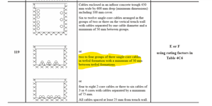
Using Table 4D3 (to run to 70C) I cannot even get Trefoil 3 sets of 4 x 630mm2 (809A) cables to work, due to a grouping factor of 0.54?
How is the dealt with practically?