
Anyone know how to get ZE from Scottish Power
I am just getting the run around….

As a matter of interest, how precisely can Ze be measured and with what? I am not thinking of my MFT here.
One for Geoffrey Blackwell methinks!
I've previously posted concerns about the calibration certificates for EFLI testers whose lowest tested value could be 1 ₼ (I can't see Ohm in the “special characters” table above) when most test results fall below this value and thus outside the calibrated range………………………..
Regards
BOD
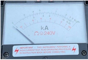
now that analogue scale topping out at 20kA on the boskiest range, makes it clear that is the ‘here be dragons’ part of the curve, as all the high current lines on the scale are compressing to the full scale deflection. (look at it and you can easily tell 3kA from 3.2kA, but the gap is about the same as 15kA and 20kA try and I challenge you to separate 18kA and 19kA with out worrying about the thickness of the needle and parallax.)
A digital meter hides that increasing uncertainty it the low resistance end from you, but really it is still there.
I suggest the high range on this is not really high enough for the OP, and a larger test current more than the 20-30 or so amps this uses is needed.
None of these are really the way to “measure” this Ze. It is best done by the analysis I suggested above, the resistance to the N - E link. Any suggestion that this has anything to do with real “Earth” is illusory. Does anyone remember the definition of a Ze value, or the Earth loop? 313.1 and page 41 (BS7671:2018).
In reality, it does not matter what the value is, it just needs to be low enough to ensure disconnection of an Earth fault at whatever the current level CAN BE at a particular point in the installation. Close to this supply transformer it can be very high indeed, further away the current falls rapidly due to cable resistance, and this is why the N-E link may be at the local switchboard. A short at the transformer will be protected by the HV CPD, at perhaps fuses or circuit breakers of about 20 or 25A for a 500 kVA TX. The primary current will be about 15A at full load, the secondary about 750A. Pro-rata obviously for larger transformers. You can easily calculate all these yourselves, it's not rocket science. The transformer short circuit current is set by the winding resistance and leakage reactance, both available from the manufacturer data.
We're about to take you to the IET registration website. Don't worry though, you'll be sent straight back to the community after completing the registration.
Continue to the IET registration site


