This discussion is locked.
You cannot post a reply to this discussion. If you have a question start a new discussion

Regenerative Drives - Effect of Power Factor

Former Community Member

I am working on a small 16kW hydro system which is experiencing about 15% loss in the Regenerative VSD. To maximise efficiency the turbine operates at variable speed. The VSD controls a synchronous generator and supplies the grid.

The VSD is a Siemens G120. The datasheet states that the efficiency should be around 96%, whilst also stating that the Power Factor is 0.9. I am looking to replace this drive for an ABB ACS 880-11 which has similar efficiency but a unity power factor.

Firstly can I trust these datasheets since, I assume, they relate to the VSD delivering electrical energy to a motor rather receiving it from a generator? Is there an efficiency penalty for regenerative generation?

Secondly, with all else being equal, will the drive with a unity power factor equate to more electrical energy on the meter than the drive with a 0.9 power factor? 

Thanks


  • Former Community Member
    0 Former Community Member

    The VSD does provide data however there are over 3000 parameters and various values for currents / power etc. It does seem that the VSD does agree with the meter, but not exactly. The meter power is the important value since this is what the income is based on. 

    Understanding where the power is being lost is becoming a big headache as there seems to be no evidence we are losing it as heat.  

  • I can see several problems here. You said above “true RMS sampling rate of 64 samples a second”. You also say the meter measures kW, not kVA. I assume you are using a scope that can do a true RMS multiply of two traces that measure the voltage, and the current. The power meter cannot produce a proper result at 64 samples a second, and the waveform out of the inverter will be some kind of chopped thing at several kHz, so that sample rate is inadequate, as per Nyquist, so the result is probably meaningless.

    You have also assumed that the VSD is efficient in braking mode and that your PM motor characteristic is similar to an induction motor, which it cannot be in terms of slip. Is this VSD intended for PM motors? I suspect that the meter does not respond well to the very curious VSD waveform when returning power to the mains and that the return path PF may also not be 1.0 as you are expecting. 

  • A note to Adrian.

    Using an induction motor will generate power, but you need to consider the rotor cage loss and therefore the efficiency. Your equations will need a significant level of “calibration values” to correctly read the true dyno power, and you might find it easier to measure the speed and torque directly, and just use the motor as a brake. You can measure the torque with no moving parts by mounting the motor on load cells and measuring the difference between the two sides under load. Rotation speed is easy!

  • davezawadi (David Stone): 
     

    A note to Adrian.

    Using an induction motor will generate power, but you need to consider the rotor cage loss and therefore the efficiency. Your equations will need a significant level of “calibration values” to correctly read the true dyno power, and you might find it easier to measure the speed and torque directly, and just use the motor as a brake. You can measure the torque with no moving parts by mounting the motor on load cells and measuring the difference between the two sides under load. Rotation speed is easy!

    Hi David,

    Thank-you for the constructive comments. Considering the rotor cage loss is something that I hadn't yet thought about.

    The rig will measure the ‘mechanical’ power, as the product of speed & torque (speed from an inductive pickup (or shaft encoder, not decided yet) & torque from a loadcell via a torque arm - the motor being trunion mounted). I'm fairly happy with the fuel to mechanical power bit of the equation.

    The end user/requester of this rig seems to have a particular fixation with regeneration onto the mains via a VSD. I think he believes that this is how a ‘real’ diesel generator would be connected and he wants to mimic this. I've tried to explain that this isn't how a genset is sync'd onto the mains & exports real power (don't want to even start to discuss reactive power). There are a couple of VSD manufacturers that claim to be able to measure the exported power in regen mode, but I'm struggling to pin them down on accuracy. As others have said, normally regen is just used as a way to increase efficiency by recovering energy when retarding a spinney thing, for the OPs application & mine the system will spend the majority of its time in regen mode.

    I think Client just wants to see that the energy is leaving the system by flowing back onto the mains (as opposed to being lost as heat in a eddy brake or water dyno). The VSD/motor is also used to turn the engine over in order to start it (not talking huge engine here, 10HP is the working figure at the moment) so some elements of the control system will need to watch the torque switch signs as the engine fires & begins to drive the motor. It will also need to watch the torque flip back again if the engine runs out of fuel or stops firing for some other reason.


    Adrian


  • Former Community Member
    0 Former Community Member

    The scope measures the true RMS of the voltage and the current and multiplies to get the power. The waveforms between the generator and the VSD are chopped at 4kHz resulting in an irregular waveform so this is the only way to get a meaningful result. 

    On the grid side, where the meter is, the VSD has to deliver power at a voltage that matches the grid, otherwise it'll go bang. The VSD can control the current exported to the grid so I can see how it is conceivable for this waveform to be irregular. With regards to the 64Hz, I am simply quoting off the datasheet. I would assume for regular sine waves this is OK but when you start introducing irregular waveforms this becomes an issue? 

    The VSD is commissioned for a permanent magnet synchronous motor. The generator nameplate data is all correctly entered into the drive. Siemens have looked at the setup of the drive and have not noticed anything wrong. So the concern is the drive is unsuitable for high efficiency regen export.  

  • Former Community Member
    0 Former Community Member

    I have taken some time to consider the concerns about the meter which are valid and I will look to get the scope on to check the waveforms. I have however had a look through some data taken from the drive itself and this seems to confirm the values from the meter are correct. 

    So I would like to ask if there are any other reasons our Siemens G120 PM250 drive could be operating at such a low efficiency when operating in a regenerative mode. Could this be a power factor issue or is this particular drive not the best option for our application?  

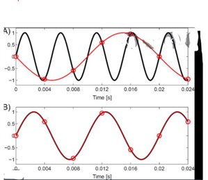
  • Hmm, well 64 samples second is not very fast, and is just one and a bit samples per cycle of the mains. Rather like the strobe at the disco, or that funny effect on films when the wagon wheels seem to go backwards at certain speeds, that is going to make accurate assessment of the current tricky. I assume on a wave that repeats perfectly at 50Hz, the sampling instant being sightly earlier on each successive cycle means the internal processor does  its sums based on  a ‘slow wave’ version of what is happening. Looking at  the plot below imagine the black is the 50Hz and the red dots are the 64 Hz sample instants, then the best guess reconstructed (assumed) slow waveform the internal processor will calculate with is the red one. When both are steady state sines, all is well, as the RMS is the same for both. I'm less sure how such a thing will handle a vaveform with stepped edges and fine structure between the samples.  

    You are of course correct, at the mains side the voltage has no choice but to be a sine wave (!) , but the current will be almost a square wave whose mark-to-space ratio is modulated depending on the power available. The RMS power will be whatever is available on the DC bus, but what the meter makes of it who knows. Perhaps a call to the makers of the meter.

    And if you are not making toast or frying eggs on it, it is not really losing 2kW, so not that inefficient.


    Mike.

    98f7fdbd946a0c80b611f8fb2cb4eaba-original-alias.jpg
  • I think it is likely that you are misleading yourself with the oscilloscope too. The waveforms are not “true RMS” they are sampled at a large number of points and then a calculation is carried out on the numbers. I suggest you refer to a textbook here and make sure you understand this properly. RMS power, the heating effect, is more complex because multiplying an RMS voltage by an RMS current does not give the correct heating effect, depending on the exact phase relationship between the two. It is even more complex where the two waveforms are not similar, and your current waveform is certainly not a sine wave. A current of 1 amp at a point and a voltage at the same point of 1 volt gives a power of 1 Watt. However, if the voltage is zero, there is a current but no real power. We call this reactive power, and it gives the definition of power factor. I suspect that the power factor in “brake” mode is not very good, and thus your apparent inefficiency is simply caused by this error. I am sure that it is not real, as Mike says, something would be getting very hot!

  • Former Community Member
    0 Former Community Member
    I think I should clarify that since the voltage waveforms from the generator to the VSD are chopped, the power has been calculated my multiplying the voltage with the current at each instance in time and averaging aver a given number of current waveforms (since they are sinusoidal). While RMS values are calculated they aren't particularly useful. The scope has recorded data at a a frequency of 1e7 samples per second so I am confident with the result. 


    However without repeating the measurement on the meter terminals I can't be sure what the reactive power is and I only have the True Power available to me. The datasheet suggest for our drive the power factor is 0.9. If this is the case there is 10% of the apparent power which isn't being converted into useful True Power which is what I want to maximise. 


    If the 2kW is not being lost as heat (since we can't feel it) then surely there is reactive power at the meter. 


    It does appear that changing the drive to one specifically designed for efficient regenerative operation could resolve this but not before measuring the waveforms on the meter terminals.
  • err no - 100% of the true power is already there - the 10% reactive power is not useful in the sense it is not something you can phase shift from imaginary to reality and then use it to boil a kettle for tea.

    In a traditional L-C world, on the wires between a load with a poor power factor and a phase shift network to restore it, energy is bouncing back and forth between the two reactances, but not much of it is  being dissipated except at the load.

    To help with the visualization consider this analogy. In many ways there is much in common with the space in a laser cavity.

    Consider the photons buzzing about trapped between 2 mirrors of perhaps 89% reflection, 10% transmission and 1% loss  - numbers for easy sums only . In equilibrium there may be light at a power of 1kW bouncing about in the cavity, and the light intensity, or no of photons, between the 2 mirrors matches that, but coming out of the mirrors bazooka-like is just 100W at each end, (10% transmission means that 10% of the stored energy gets out on each bounce, remember)  and the mirrors themselves heat to the tune of 10 watts each (1% loss) the rest, the 89% just joins the new power coming in and heads off to the other mirror to try and get out another time….

    Now the real power that is coming into the system is only the 220watts - we only have to replenish just enough energy to replace those photons leaving as the wanted beams plus the energy dissipated on the mirrors. (plus any cavity loss, neglected here).

    The apparently higher level of energy bouncing about reactively is only there as stored energy, built up over many cycles. Sure if you blew one of the mirrors off a few seconds after switch on you could get just the one cavity full of stored energy but that would be it. (such things as Q-switch cavity dumper lasers do actually exist by the way, and routinely fool the folk trying to look at the safety case from a peak power perspective...)

    So much for the simple optical system. 

    In terms of power factor,  you will usually have transmission coefficients (representing the ratio of the stored energy levels, as I2L/2 or  CV2/2  to the power dissipated or arriving from the supply ) nearer 50%-100%, but the science and the maths is un-altered - the stored energy in the inductors or capacitors is cycling in and out over the cycle period but as you end up where you started after one cycle, having to put back in as much as you took out, that energy is not actually available to burn. If anything the electric case is less extreme as the stored energy per cycle may be less than the dissipated, the ‘Q’ factor of stored to burnt can be less than 1. In a laser there is always a lot more stored then used so it is more obvious.

    The equivalent of the laser cavity dump has you cut the wire to the PF correction caps at the very instant that their voltage peaks, and then walk off with them - you get one lot of CV2/2 to play with and then it's gone. (this is a thought experiment, do not try it ! )

    Mike