This discussion is locked.
You cannot post a reply to this discussion. If you have a question start a new discussion

55v - 110v centre tap transformer short circuit calculations

hello

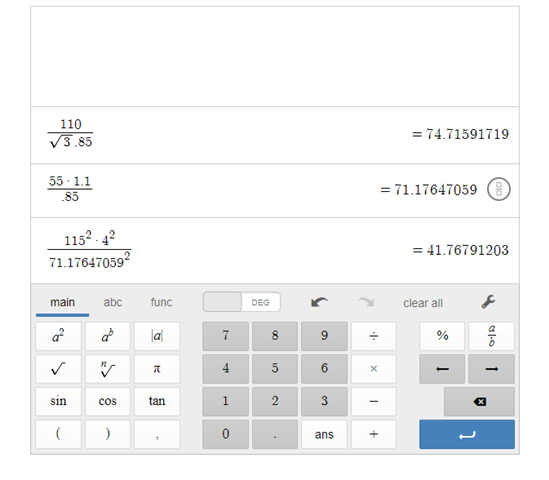
i have been trying to work out how to work short circuit calculations for 110v systems. do i use 55V with c max or do use 110v or even use a 3phase calculation. i am trying to work out if a circuit will trip on 16A c type mcb for short circuit as i am putting a rcbo in to cover the fault current. 

110v 55v 

0.85ohms line to line tested

4mm 2 core cable 


  • It depends on which fault you're considering. A L-PE fault on a 55-0-55V system will be driven by 55V, while a L-N fault (really a L1-L2 fault) will be driven by 110V. It's then a matter of identifying the worst case for each of the situations you need to calculate for - for ADS (if needed) it's probably the time to disconnect on a L-PE fault that's critical, while for energy let-though (protection of conductors) the L1-L2 might be the worst case especially if protection is by MCB rather than fuses. You could probably do worse than calculate everything for each situation and see how the numbers look, to get the feel of things.

    3-phase RLV system would be 63V L-PE and 110V L-L so I'm guessing you're not looking at one of those.

       - Andy.

  • Thanks it turens out that i needed to do it to 110V so the equation would be 110v*cmax / Zs. i reconfimed this with my multi meter. 

  • What kind of multi-meter are you using and what are actually measuring?

  • Both!

    The prospective fault current for a line-to-line fault will be twice that for a line to cpc ("earth") fault.

    Cmax (or possibly Cmin if you are using circuit-breakers, dependent on the I2t curves) applies to both. The difference comes with the adiabatic criterion, although which will be worse could depend on whether you are using circuit-breakers or fuses.

  • I suggest that the 110v case and the resistance of a short lead gets the highest fault current, but 55V and the longest lead on the drum gets you the lowest fault current - and I presume you'd like the breaker to still operate in both cases.

    Note that despite BS7671s best efforts to confuse matters, by harmonizing with a load of countries that do not use it, one of the really nice things about 55-0-55 is that during a bolted fault at the end of a long lead, the highest touch voltage is 28V or so, and the usual requirement for a faster than a heartbeat disconnection time for safety of life  can be relaxed, so the projection can be more for preventing the cable catching light. It is a very hard system with which to do yourself an injury.

    It is however a pity that many builders seem to trail a 13A socket on an extension lead into a convenient puddle of cement solution, and then plug the transformer in right next to the thing it supplies....

    Mike.

  • When I was a lad in the 70’s and 80’s it was a common belief that you had to run a long 240 volt lead to the transformer then plug the tool directly into the Tx, because otherwise there would be excessive voltage drops is you used long 110 volt extension leads.

    There were a considerable number of times I was told I was wrong to use long 110 volt extension leads rather than long 240 volt leads and had the Tx in the wrong place.

  • Why 4.0 mm two core cable?

    What is the output rating of the transformer?

    Does the transformer already have fuses in it on the output?

    Is it a fixed installation or temporary?

  • Why 4.0 mm two core cable? the transformers and sockets where updated some years ago and the guy here just reused the cable. 

    What is the output rating of the transformer? not to sure. probably a 5kva 

    Does the transformer already have fuses in it on the output? the transfomer has two outgoing ways 16a c double pole. 

    fixed installation

    i got .25ohms on the z at tx and .85zs at the furthest socket. the short circuit on the multimeter had a result of 142a and around 70a down to earth. the results line up with the calculation. so line to line calculation need 110v and line to earth 55v. makes scene. i just saw a calculation of phase to phase short circuit and wanted to check if that was used 

    thanks guys

  • My experience of fixed 110 volt installations has been in pub cellars with everything run in three core cable.

    So, what is the earth path from the socket back to the transformer with two core cable, is it in conduit?

    The “star” point in a 55-0-55 transformer delivering 110 volts is the centre tap in the transformer, I’m not picturing how the sockets earth terminal are connected to the centre tap. This earth is referenced through the incoming supply earth, is that what is being relied on? 

    I presume you are testing loop impedance and fault currents live using an electricians multi-function tester, rather than dead testing resistances with a multi-meter.

    In real life I have only ever seen tool transformer fuses blow due to prolonged over load, not due to a damaged cable or the like.

    When I started work a firm I worked for was using the old scratch earth 110 volt leads onsite, some of these had fuses which were actually the pin of the plug, you had to unscrew the plug pin and replace it if you blew the fuse, others had solid fixed pins so you had to ensure you laid them out in the correct order and watch what you plugged in to multi-way adapter boxes.

  • the circuits from the transformer are installed in SWA cable. fly lead from banjo to the transformer earth.