This discussion is locked.
You cannot post a reply to this discussion. If you have a question start a new discussion

Domestic consumer unit rating with PV and battery storage.

Having read the COP on  Electrical Energy Storage Systems and  completed the IET course on the same subject I had a query regarding the rating of domestic consumer units and switch gear which I addressed by email to NICEIC technical. I also came across an older discussion on this forum but am still no closer to a definitive answer. I've included my findings and would welcome constructive input. 

Post by GKenyon in previous thread

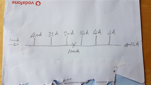
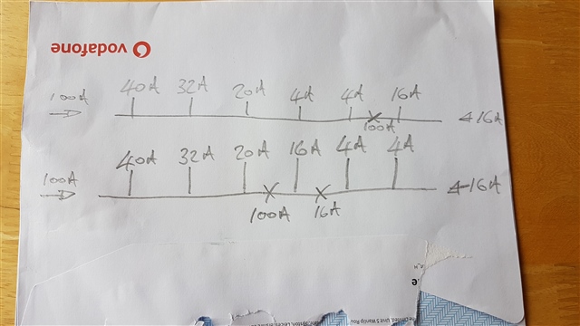
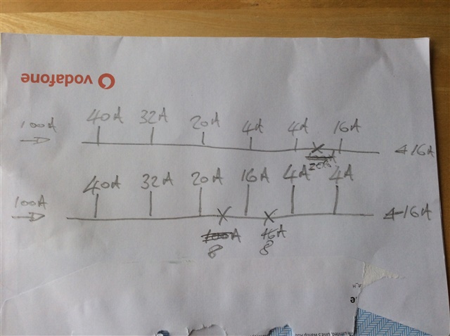
Because an EESS charges the battery as well as as discharging it, you will need to check the rating of the CU is not exceeded. For example, if the CU is rated for 100 A, and there's a 100 A service fuse, and a 16 A output battery storage system - by feeding 16 A in at one end through an OCPD, because that OCPD gets hot it contributes to the total heat load in the CU - therefore the CU should be rated for 116 A.

My question to NICEIC.

Hello
Please can you help with the following.
Domestic installations with PV and/or battery storage.
551.7.2 Where the generating set is connected to either the main consumer unit or via a separate consumer unit via Henley blocks the rating of the consumer units shall be protected by a OCPD InA≥In+Ig(s).
Where In = 100A DNO fuse and Ig(s) = 16A MCB or 2 x 16A MCB's which would be 116A or 132A, what inspection code should be given on an EICR where a standard domestic consumer unit is fitted which has a rating of 100A. Can any allowance be given on connected load being less than 100A or as the regulation relates to the rated current of the assembly and is a "shall" requirement does the load have no influence on the code assigned. 
Answer from Certsure

The Certsure Technical Helpline provides general information and guidance for compliance with the British Standard BS 7671, the Requirements for Electrical Installations, and matters concerning electrical safety within electrical installations designed, constructed, inspected, and tested to BS 7671. Without detailed knowledge of your installation, we cannot offer advice specific to your installation and can only generically provide comments based on the information you have provided.

The intent of the regulation is to ensure that the assembly is not overloaded with the additional generating set, as the main fuse may not protect the assembly if for example the internal busbar is pulling 116A.

Regulation 536.4.202 states: see regulation

From the viewpoint of an EICR, we would be looking for evidence that the assembly is being overloaded, such as burning, distorting and the likes.

The above regulation allows for diversity to be taken into account, so we can exercise our engineering judgement in declaring whether or not the assembly is suitably protected.

We trust that we have answered your current question; however if you require any further information or clarification, then please do not hesitate to contact us either by e-mail to helpline@certsure.com or by telephone on 0333 015 6628

I've read 536.4.202 and am interested on your views on the last paragraph with the shall requirement and how this ties in with the answer given by certsure. 536.4.3.2 is also relevant but has not been mentioned in the reply.

Thanks for your time.

  • To answer my own question regards a maximum demand of 175 amps on a 100 amp supply, we decided there’s nothing to code on an EICR, but an advisory note was a sensible observation.

  • Unless the inverter MCB is immediately next to the main switch without the MCBs for any other circuits between them, there will never be 116 amps of current at any point on the busbar will there?

    So doesn’t putting the inverter MCB on the far end of the busbar furthest away from the main switch solve the problem?

  • there will never be 116 amps of current at any point on the busbar will there?

    That's if you consider the problem is current flow (and possibly resistance of) the busbar itself.

    But what if it's something else?

    There is another breaker in there getting hot - another 16 A worth. Copper is a good conductor of heat as well as electric current.

    Then there's overcurrent protection of the assembly.

  • Literally back of an envelope,  MCBs may need derating and I would not want to be paying the £5 per hour electric bill for the 23 kilowatt load for long.

  • But when the batteries go flat and it’s dark outside the busbar and main switch as will everything upfront of them will be overloaded, but that’s compliant because of the DNO fuse.

  • Reconfigure that as on the top line with the 16 amp load on the end next to the inverter MCB and the busbar will never be overloaded whilst the inverter is feeding in 16 amps, will it?

    I was adding the total loads up across the breakers, that’s not the actual current being carried in the busbar, in the top diagram where it says 100 amps the current is zero and in the bottom diagram 8 amps. I had to stop and think what I meant myself.

  • So putting the inverter 16 amp MCB at the far end of the busbar with a MCB for a circuit rated at 16 amps or more immediately next to it between it and the other MCBs solves this particular issue.

    But the consumer unit is going to be excessively hot unless the design and layout is carefully considered, plus I would want to be paying the electric bills.

  • That's if you consider the problem is current flow (and possibly resistance of) the busbar itself.

    But what if it's something else?

    There is another breaker in there getting hot - another 16 A worth. Copper is a good conductor of heat as well as electric current.

    In theory yes. Yet the Irish put a DP MCB in as their incoming device in their CUs - so that's an extra 200A worth of heating (100A in each pole) - even considering their CUs are often a little bigger (two rows) they're not three times the volume or have three times the surface area - so the heating effect from MCBs would seem to be small.

       - Andy.

  • This is the point I throw in a link to the Hager Australian website for the information about derating their protective devices and point out you cannot put lots of fully loaded MCBs or RCBOs in a consumer unit all tightly packed together on the same busbar, they get too hot.

    www.hagerelectro.com.au/.../TECHINFO_MCBS.PDF

  • InA is directly related to temperature rise in parts of the assembly, when undergoing tests according to the product standard.

    We can clog up this thread all day long with discussion about it, and whether BS EN 61439-1:2021 ought to take another set of criteria into account, but it won't change the fact that manufacturers will expect you to take 551.7.2 into account when connecting generators through OCPDs in a consumer unit to that standard.

    551.7.2 also means that, as a battery storage system is a load as well as a generator, the cable connecting it has to be "double rated" ... which may well mean you can't get it into the terminals on the battery storage inverter! (Doesn't apply to Solar PV as that is classed as "one direction only", generator only, no load - 722.551.7.2)