This discussion is locked.
You cannot post a reply to this discussion. If you have a question start a new discussion

Where can a PV array be connected?

I suspect that a PV array would normally be connected between the meter and the first DB, but can it be connected more peripherally please?

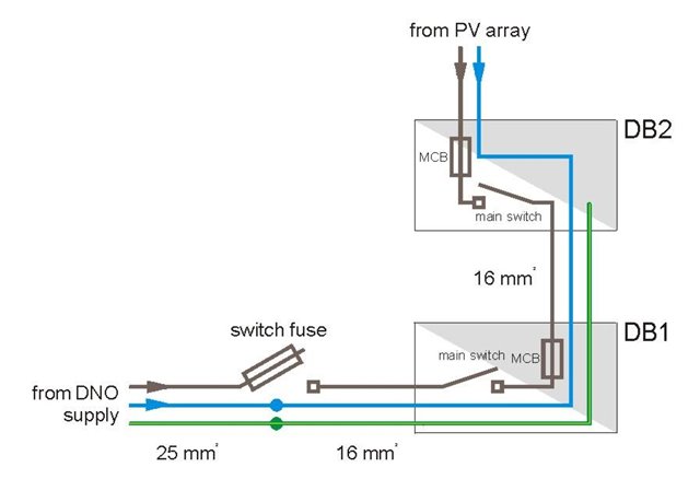
The most suitable area of roof is at the opposite end of the premises from the electrical origin. However, there is a small DB with spare ways adjacent to the loft space. It supplies one lighting and one socket circuit and is seldom significantly loaded. The distribution circuit from the main DB is 16 mm² singles (with the live conductors being sheathed). As far as I can see, it travels through under-floor voids and is boxed in with other services as it ascends in a bathroom so RCD protection is not required. If the inverter can be situated in the loft space then only a short length of AC cable would be required.

This is what I have in mind.

  • I’ll throw this in, then go for a walk to see my dad.

    www.electricalsafetyfirst.org.uk/.../best-practice-guide-3.pdf

  • Puce we droid disturbances such as induced vollage surges caused 0y lighting.

    551.7

    Additional requirements for installations where the generating set may operate in

    parallel with other sources including systems for distribution of electricity to the

    public

    551.7.1

    When a generating set is used as an additional source of supply in parallel with another source, both

    of the following conditions shall be fulfilled:

    (i) Protection against thermal effects in accordance with Chapter 42 and protection against overcurrent in

    accordance with Chapter 43 shall remain effective in all situations

    (ii)

    Where an RCD is providing additional protection in accordance with Regulation 415.1 for a circuit

    connecting the generator set to the installation, the RCD shall disconnect all live conductors, including the

    neutral conductor.

    Ref. BS7671:2018:A2:2022 (inserted using scan text)

  • Ah yes, but that isn't allowed (according to the guide) for PV. Option A seems to demonstrate that an RCD can be used in both directions. See page 11.

  • Puce we droid disturbances such as induced vollage surges caused 0y lighting
    Been a digetistin of the Prof Stanley Unwin guide the most homey eletrickery perhaps
    ?less  muchley  comprehensibible
    is all I can say

    Mind you some of the regs might as well be also

    Mike

  • This RCD appears to allow for flexibility when deciding how to wire it.

    Proteus RCBO 6 Amp 30mA Type B 6A B6 Compact 6MBRSPK NEW - Willrose Electrical - Discontinued & Obsolete Circuit Breakers (willrose-electrical.co.uk)

    Not so with this RCBO, so the manufacturers need to be consulted.

    Now, our European cousins tend to power MCBs from the top down, so we tend to assume we can supply from the top, but it's not a foregone conclusion.

  •   

    we have to try all the features on this website and our devices such as my Ipad, it would be wrong not to.

  • I had had a “moment” a couple of weeks ago.

    A socket circuit had blown its wire fuse in an old BS3036 fuse board, because it was in a very poor condition, there’s a double pole 30 mA RCD upfront of the fuse board. Having completed a couple of repairs to the circuit I replaced the blown fuse with a spare plug-in MCB out of my van, then did a loop test and an RCD test.

    With the installation “isolated” by the double pole RCD that I had tripped with my Megger MFT1741 I reset the tester to do a loop test on a different socket and check polarity, but it displayed 98 volts and went into one of those diagnostic apps sequences where it indicates voltages between different conductors.

    I had missed isolating the PV that feeds into the installation downstream of the DP RCD, I didn’t try to determine if it was phantom voltage, but I doubt it was, I got the power back on scribbled some comments about recommendations to upgrade the existing installation on the MWC and got out of there.

    I have had odd voltage readings before in installations with PV, yes if you isolate the PV and the mains there isn’t any voltage, but if you put it into tripped after a fault condition then you can get odd voltage measurements.

    Having said that the worst I have experienced was a PV and battery installation where the installers had installed a four pole switch as a dual supply isolator that disconnected the installation live, but livened up the neutral, so the installation appeared to be dead but both the line and neutral had 240 volts on them, as well as the live and neutral bars in the consumer unit, because the neutral was being back fed then the live was back fed through the connected appliances.

    https://www.tlc-direct.co.uk/Products/WYNHDSREC4.html

    There are actually some scary PV installations out there.

  • But that will be longer than the breaking time alone so ADS times need a re-visit.

    Usually not an issue - once the DP RCD has tripped, the PV becomes a separated system - the inverter may still be putting 240V L-N but as nothing is referenced to Earth, the shock risk (to Earth) is eliminated.

    For MCBs the disconnection time is less onerous as the circuit to the inverter is by definition not  a final circuit (it doesn't directly supply current consuming equipment) so despite it's low rating (e.g. 16A) only needs to meet the 5s disconnection time requirement (for TN).

       - Andy.

  • When electrons were more of a novelty and voltages more variable and a domestic generator needed fossil fuel,  you often found moving coil meters  built into or beside the private genset to give a visible indication of generation - partly I suspect to impress the natives and justify the price but hey ho..

    Thinking about the problems of being certain that things with multiple sources are really on or not, with sources that do not make helpful chugging noises or create smoke to indicate generation in progress, that  perhaps now, given that  digital volt meter modules have never been cheaper, it might be a good idea to have something with an LED display or similar to show that the inverter really is inverting, or failing that a pilot light in or beside the CU. - actually I've thought that before with off peak supplies as well , that a little neon light to show that the cheap rate is on or not would have not cost very much as part of the CU .

    Mike.

  • Well said that man!