This discussion is locked.
You cannot post a reply to this discussion. If you have a question start a new discussion

Where can a PV array be connected?

I suspect that a PV array would normally be connected between the meter and the first DB, but can it be connected more peripherally please?

The most suitable area of roof is at the opposite end of the premises from the electrical origin. However, there is a small DB with spare ways adjacent to the loft space. It supplies one lighting and one socket circuit and is seldom significantly loaded. The distribution circuit from the main DB is 16 mm² singles (with the live conductors being sheathed). As far as I can see, it travels through under-floor voids and is boxed in with other services as it ascends in a bathroom so RCD protection is not required. If the inverter can be situated in the loft space then only a short length of AC cable would be required.

This is what I have in mind.
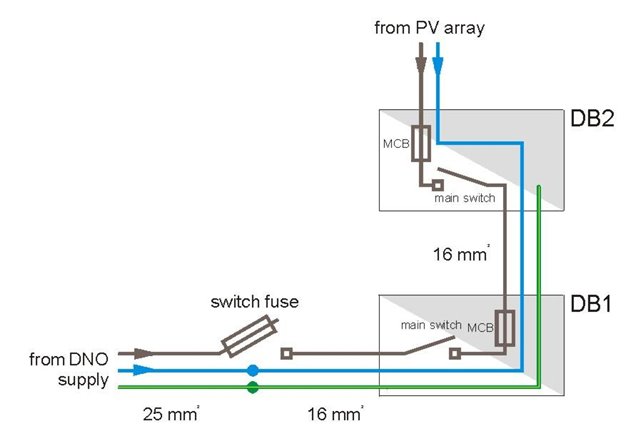
  • Yup - looks like one of the bits of bus-bar has drifted to the wrong end. I'd expect Grid and PV to come in at one end and links and the main CU connection to be at the other. Electrically I suppose you could have one pole (N or L) connections (but not the actual switch) 'upside down' as it were - it would work the same, but would be a lot less obvious to wire up.

        - Andy.

  • Yup - looks like one of the bits of bus-bar has drifted to the wrong end.

    I hadn't appreciated that the tabs are wee busbars. Yes, both should be on the load side, which is in accordance with the diagram. (Should they be in the terminal tunnels?)

  •  (Should they be in the terminal tunnels?)

    Probably not - with some brands, including Wylex, connections can made either in the tunnels or using "fork" connectors under the screw heads ... or both. Fork bus-bars can be quite handy as you can link devices under the screw heads and still have the whole tunnel terminal for connecting cables, that way there are no problems getting both a bus-bar prong and a wire into a single hole and have them both clamped properly.

       - Andy.

  • Ah that drawing suggests it is for splitting one incomer into two supplies - perhaps one to a CU and one to generator that is mains synchronous, and never run as an island. Then the bits of bus bar should be both at the 'incomer'  end.

    It could be made a lot clearer.
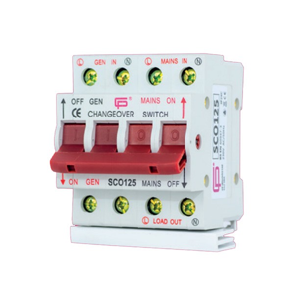
    Actually I'm not sure that wylex do the change over type with the up down reversal but lewden and others like these chaps certainly  do.
    And this 'cheap' one is what I would consider to be well labelled.

    Mike

  • Ah that drawing suggests it is for splitting one incomer into two supplies - perhaps one to a CU and one to generator that is mains synchronous, and never run as an island. Then the bits of bus bar should be both at the 'incomer'  end.

    Or to combine two supplies - Grid and PV enter at the top, bus-bar and connection to normal CU at the bottom?

       - Andy.

  • Without being able to have a proper look, the wee busbars look a bit feeble for 100 A.