SWA plus separate cpc

While on a site last week, I noted 25mm2 4-core swa cables being installed on a ladder and for some reason, each one had a 10mm2 separate copper cpc cable tied to the swa. The furthest run is about 50m from a DB where the EFLI is 0.1 ohms.

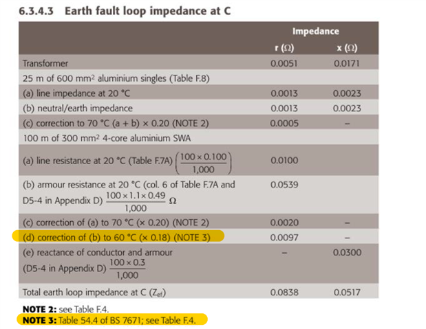
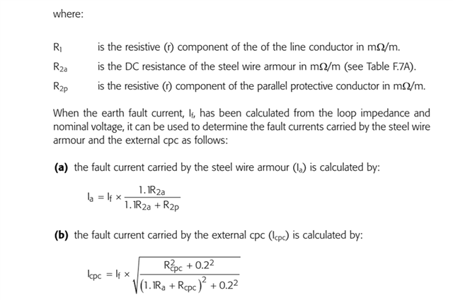
Just as an academic exercise, I set about trying to establish the current division between the wire armour and the separate 10mm2 copper cpc using the formulae in the IET Design Guide. Factoring in the usual temperature increases, 70 for phase in the swa, 60 for the wire armour and 30 for the separate cpc, the expected impedance was 0.25 ohms with a fault current (using 230) of 1140A dividing to 672A in the wire armour and 826A in the separate cpc.

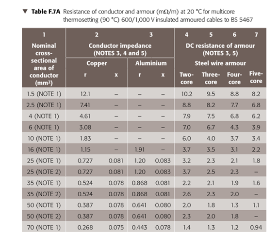
Data used; R1 at 20C = 0.73mohms, R2a at 20C = 2.1mohms and R2p at 20C  = 1.83mohms. Likely there is no real merit in the pedantic adjustment for temperature, but hey!

If someone felt sufficiently bored and had an old fag packet, would they be kind enough to check my results? Strangely, if one reduces the separate cpc to 2.5mm2 the fault current is 936A dividing to 244A in the wire armour and 727A in the 2.5mm2 separate cpc. That is counter intuitive but perhaps expresses a limitation on the formulae or, much more likely, a limitation on my understanding!

  • I agree with most of that.

    There are times that a parallel cpc can be needed such as bonding in some situations, disconnection times, etc – but, in general, they not required provided the cables are properly installed. I would add a copper connection to the earth terminal via a banjo washers as well as the other measures to ensure a good connection.

    As to the micrometer and the axe, I definitely agree. We should bear in mind that cables come in discreet sizes so a calculation that indicate that an 82.345 mm2 cable is required are a waste of time – a quick calculation using a simple model might lead you to a 95 mm2 cable in one hit .

    Regards

    Geoff Blackwell

  • As to the micrometer and the axe, I definitely agree. We should bear in mind that cables come in discreet sizes so a calculation that indicate that an 82.345 mm2 cable is required are a waste of time – a quick calculation using a simple model might lead you to a 95 mm2 cable in one hit .

    Yes but if you are a contractor and a simple model says the cable should be 97.65mm2 and requires you to use 120mm2, you might be grateful for the micrometer approach that confirms you can use 95. 

  • Graham, setting aside Fowlers statement on pedantry, I believe this is where the 60C is justified;

  • No you just tweak one of the parameters so the answer becomes 95!!!!!!!!!!

  • Graham, setting aside Fowlers statement on pedantry, I believe this is where the 60C is justified;

    A little care, perhaps, is needed here ... these are tables for K for the stated values of initial and final temperature (see top of page 200, in 543.1.3, 'The values are based on the initial and final temperatures indicated in each table.'

    That does not mean that every cable has those initial temperatures ... it may be a "good enough" assumption (the tables say they are "assumed" initial and final temperatures) for the adiabatic criterion, but that doesn't mean one shouldn't err on the side of caution when trying to establish whether an impedance is low enough to operate a protective device effectively?

    What would the examiner expect if the cable was bunched, or installed in an underground conduit with other cables?

    In the particular case we are talking about - parallel copper cpc - these are often bunched with the cable, the assumed temperatures in Table 54.2 may not be valid.

    In the case of the example of CPEVCEI 5th Edition, the temperature correction factors used in the example for the armour are actually stated (in another table) so the reader doesn't have to work it out for themselves.

  • Using SWA as a CPC the guide for your reference. (gadsolutions.biz)

    "The use of Jubilee clips to terminate the armour is an absolute bodge"

    But what about lighting column cut-outs? https://www.lucyzodion.com/product/thm0028975-titan-single-fuse-cut-out/
    Granted it includes a brass tube to support the inside of the armour, but presumably have proved to be satisfactory.

       - Andy.

  • Graham, yes, I hadnt thought of it that way and had just slavishly followed Chief Examiner comments (and some of the older texts like BD Jenkins who shows calcs to 60 for the wire armour, albeit as an average of initial and final temps). It all becomes  unnecessarily arcane when one considers the current practice of using 218.5v that used to be 240v then 230v to calculate Zs not to mention the uncertainty of the value of Ze. I believe GB and Mike are probably spot on with that micrometer and axe analogy. 

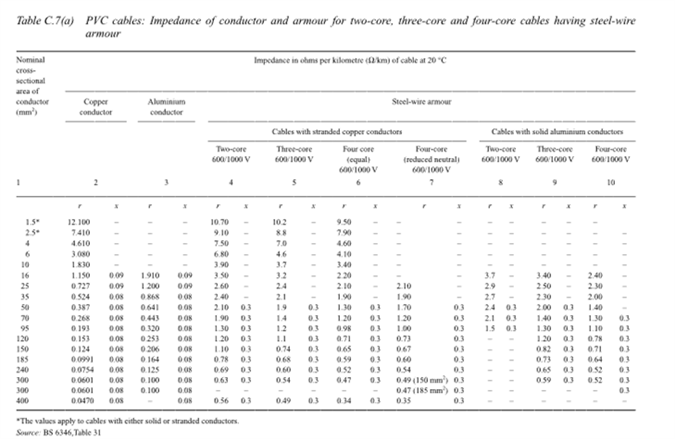
    I just spotted a howler in my own Excel calcs regarding some swa values. I have been extracting data from this table from Paul Cooks wonderful commentary on the 17th. 

    I couldnt understand why my calculations using old fashioned approach of separate r and x value was just so far apart from the one in the CPEVCEI 5th Edition until I twigged the r value for the 70C swa was significantly different to the value for 90C thermosetting given in IETEIDG. One is 3.9 and the latter 6. There must be significantly less csa of wire armour in the 90C cable?

  • Be wary of modern cables claiming to be BS6346 (the PVC clad SWA) as that standard was withdrawn over ten years ago, and the XPLE standard ' 5467 is the more common.

    Worth a read of this wiring matters article Of course there is plenty of old cable about the place. But the diameter and no of the steel wires is not guaranteed the same and can be a source of confusion.

    Except for BATT cables data, where their values are not always quite the same as those tables either. but the variation of armour resistance between their XPLE and PVC offerings is shown side by side, so is easier  to see.

    Mike

  • I am typing this for insertion below GKs post of two days ago. I dont know why the reply rarely gets posted like that and ends up at the foot of the thread. Nor indeed, does the quote button work Windows 11 PC. It does on my Ipad.

    the correction should be to 60C and should be 1.18 rather than 1.225

    I am convinced that there is a dusty room somewhere in the dungeons of City and Guilds HQ where equally dusty, bespectacled, old men pour over IET publications in search of secreted minutiae to ambush the unsuspecting candidate. Below from current EIDG.

  • Yes, I think that, assumption is absolutely fine in some cases, hence that hasn't been updated ... but not others, and in particular perhaps shared ducts for EV charging which is the other example quoted.

    I agree with your suggestion that some more examples ... perhaps with the various assumptions used noted, as here ... would be of great benefit to everyone concerned.

    At the last update, we were trying our best to move the publication on to align with PD IEC/TR 50480 because of a number of issues relating to calculations, and following the update/withdrawal of some of the armoured cable standards, and the data they provided.