Draft for Public Comment - IET Open combined protective and neutral (PEN) conductor detection devices (OPDDs)

The IET's new Standard (IET 01) includes definitions, requirements and tests for open PEN detection devices (OPDDs) and is now open for public comment, find out more here https://electrical.theiet.org/get-involved/consultations/iet-open-combined-protective-and-neutral-pen-conductor-detection-devices-opdds

Deadline for comments: Friday 2 February 2024.
  • A device that reports back to the DNO so they could investigate areas they are getting multiple "pings" from, would be far more effective.

    I very much agree with this concept.  Kit that alerts the DNO/DSO to faults in their network

  • So data could be passed onto the appropriate DNO just as easily (and apparently some DNOs are getting power loss data and have been acting on it - e.g. sending someone out in a van to berate whoever had pulled the service fuse without authorization).

    2 points for the DNO/DSO/MO

    1)  Provide a 2 pole or 4 pole isolarion switch at origin of install and the electrician will not need to pull the main service fuse to comply with the EAWR.  (2 pole for single phase or 4 pole for 3 phase)

    2)  DNO/DSO/MO should join this forum and participate in these discussion and see that there is a need for a SMETS2 upgrade or a new SMETS3 meter that can detect and report PEN faults on their networks.

  • I've been pondering the Protective conductor current (M3) detection method. On the surface it seems like a very good idea - given that basic L-N voltage monitoring to detect open PENs has some gaping holes in it when fed from a 3-phase distribution system.

    Anyone know why 21mA was chosen? - seems a odd given that most existing RCD designs & components will be based on 30mA (with actual tripping >15mA ≤30mA) seem to be in the same ballpark and normally proves adequate for additional protection.

    EV c.p.c.s look to be quite "interesting" in terms of the current they may carry. As well as conventional fault currents and the normal AC leakage currents (e.g. filters on the AC side of the charger) there's presumably the possibility of some DC components in there from various sources. The PP and CP lines are mostly DC and return via the c.p.c., but I presume the intention is that the monitoring should be upstream of the return connection point though - to avoid those currents in normal service. Plus of course the current resulting from a raised PEN potential running to Earth via someone touching the car - which is what we're trying to detect.

    Presumably all these other currents have the potential to desensitize or blind a coil monitoring the c.p.c. in the same way as in a normal RCD? So should we be looking for "types" of monitoring that mirror the RCD requirements for EVSE? e.g. A-type minimum (or possibly F-type considering one of the pilot lines can carry a 1kHz signal?) and B-type if there's nothing to prevent d.c. components of the current exceeding 6mA?

    Also am I right in thinking the method won't work well with charge points with exposed-conductive-parts that are in contact with Earth (or an extraneous-conductive-part)?  e.g. most public charge points (either stand alone or bolted onto lighting columns). If the monitoring only covers the c.p.c. out the vehicle, then there's no protection for someone touching the charge point (and going to all this effort to protection someone from shock when they touch the car seems a bit pointless if they're going to run exactly the same risk when they try to plug in or unplug it from the charge point). And if the monitoring includes the connection to the charge point metalwork, it's going to nuisance trip so often as to make it unworkable? (e.g. if the charge point had a resistance to Earth of say 100 Ohms (probably not unreasonable for something embedded into concrete in the ground)  the PEN would only have to get to 2.1V from true Earth to have 21mA flow - e.g. PEN voltage drop along DNO PEN line alone can often be much higher than that in normal service.

       - Andy.

  • true. And there are credible fault scenarios with damage to the charging leads where the uni-polar square wave "pulsed DC", if you like,  in the cable out to the car does enter terra -firma, and some fraction of it does sneak back via the supply side wiring as well, so we cannot assume 'never' for the  pilot signal ending up 'visible' and confusing to the rest of the ADS.

    It is fair tp say that all of these 'M' methods have some blind spots - which is why there is no clear winning method.

    Mike.

  • Could people check my thinking on this please? I've been ponding how the L-N voltage monitoring approach might be able to distinguish broken PENs from other kinds of faults (e.g. L-PEN shorts) - as broken PENs should usually taken more seriously (either disconnect quicker or be more reluctant to re-connect).

    My train of thought goes like this (with plenty of assumptions):

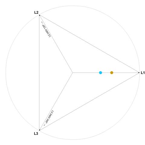
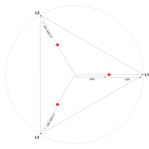
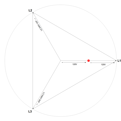
    A L-PEN fault (or L-N or L-PE within an installation) - presuming fault of negligible impedance etc., and on a TN system of course will, tend to turn the supply conductors into a potential divider - so (presuming equal sized conductors) we get about half of Uo at the point of the fault. On that phasor diagram, a fault on L1 would be at the red dot:

    we'd see the same at points downstream, but view from things tapped off upstream, the L & N conductors would still have some voltage difference between them:

    so I notice that N could be closer to the centre, but never further away than Uo/2.

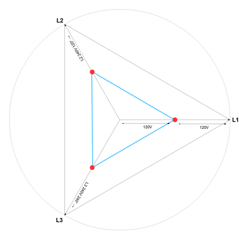
    Similarly considering faults on L2 or L3:

    so we get a triangular area within which N must remain for L-PEN faults.

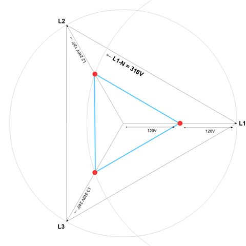
    So viewed as a voltage difference from our chosen line (L1 in this case), is it fair to say that the L-N voltage can't exceed the distance to the furthest point of that triangle from the end of the L1 vector?

    Or in other words, if L-N exceeds (say) 318V, then we must have an open-PEN event? (OK, plus or minus a chunk to deal with Uo not being precisely 240V, and a few wobbles for inductive things happening), but as a general principle?

    Of course there will be other characteristics too (typically normal shorts should be cleared pretty promptly, whereas open-PENs can go on for hours), but if we were looking for something that if present could show immediately that we were definitely seeing an open-PEN event, would this do?

        cheers

               - Andy.

    (tweaked for less transparent diagrams)

  • For pure resistive faults I agree with this logic and inductance is not really a issue until we get to the really fat cables where R is so low the inductance starts to take effect.
    Of course we could be on the faulty branch that gets the reduced line voltage ;-)
    And, how much do we care if our fault detector disconnects for the wrong kind of fault - my feeling would be that a false positive trip may be prefferable to a false negative non trip of an open PEN were for some reasons of lucky load balance the voltage pull is not so great.

    And of course there may be an over-voltage due to something else happening at the supply side. but that is likely to be very short lived - the transformer cores wil saturate if there is much of an HV over-voltage.

    Mike.

  • And, how much do we care if our fault detector disconnects for the wrong kind of fault

    That's something else I've been pondering - I'm probably biased in that at home we suffered from a couple grumbling DNO cable faults over the last few years - each one took literally months to finally locate and fix properly. So we went through many events where the lights would flicker a few times, or the power go off for a few minutes. If I'd had an EV and each time it had happened overnight I'd woken up to an unusable car I wouldn't have been happy.

       - Andy.

  • For pure resistive faults I agree with this logic

    thanks taking the time Mike - much appreciated.

       - Andy.

  • One more thought (I know it's a bit late for the DPC, but just in case it contributes to the wider debate...)

    Method M3 - open "When the protective conductor current is 21 mA or more". I presume the idea here is to protect against current flowing from the (possibly hazardous MET/PEN) to true Earth via someone touching the car while in contact with the general mass of the earth. (Mostly to protect from open-PEN situations that the L-N voltage method doesn't detect). I'm wondering if measuring the current in the c.p.c. alone is actually a good proxy for what could be flowing through a victim - after all current can arrive on a c.p.c. through a number of routes - e.g. from the EV itself, or the wall mounted controlled, by leakage current or even uncleared faults - and furthermore current returning through the c.p.c. won't be passing through the victim (possibly increasing the chances of nuisance trips?). Has 21mA been chosen rather than say the more conventional 30mA to allow for leakage current? Is 9mA a reasonable assumption for that?

    My thought is that what we're really looking for is current that's flowing along the c.p.c. that isn't part of the normal circuit 'return' current (including leakage, L-PE fault currents etc) - so would it make sense to do that by feeding all three wires (L/N/PE) through an RCD? In this case a normal 3P or 4P off-the-shelf 30mA one of an appropriate type would suffice. Of course the RCD wouldn't trip if the L-N voltage was low, but in that case the L-N voltage mechanism (M2) would have opened everything including the .c.p.c. anyway, so that's OK I think.

    Maybe M3a - measure the c.p.c. for ≥21mA
    M3b - L/N/PE imbalance of ≥30mA.

        - Andy,

  • My thought is that what we're really looking for is current that's flowing along the c.p.c. that isn't part of the normal circuit 'return' current (including leakage, L-PE fault currents etc) - so would it make sense to do that by feeding all three wires (L/N/PE) through an RCD? In this case a normal 3P or 4P off-the-shelf 30mA one of an appropriate type would suffice.

    The standard isn't there to tell the manufacturer precisely how to design and manufacture the product, just the relevant parameters it ought to meet.

    I'm sure a similar approach could be taken to actually building a product, but perhaps this would be "mis-use" of a COTS 3P (three-phase) RCD for single-phase, and whilst a 4P (TP&N) RCD might appear to do the trick for three-phase:

    • it doesn't contain 5 contacts to open if the arrangement is TP&N; and
    • whilst there is a contact to open N, I'm not sure they all pass the N through the sensing coil (and I don't think it's necessary either) - so if that were the case and we decided to use the 4-pole device for TP+PE (as it were), it wouldn't pass the PE through the sensing coil to detect current flowing from the grid to the person (i.e. from the raised PEN voltage at the installation, and not via L1, L2 or L3 supplied to the EV).