I'm currently installing a heat pump and noticed that some of the manufacturer's information says of the RCDs to be used with it:
...now requires the use of a Type B RCD/RCBO with the following specification:
-
Minimum detection capability up to 20 kHz
-
Minimum trip threshold of 150 mA above 1 kHz
and looking at the devices the manufacturer suggests, these seem to be nominally 30mA types.
So it seems to me these suggested devices may trip at 15-30mA at 50Hz, but may tolerate more than 150mA above 1kHz.
My first thought was where does this leave me with respect to section 543.7 (equipment having high protective conductor currents)? Can I assume that the 10mA limit only applies to 50Hz currents? or given the way the words are written should it be read as applying to all frequencies?
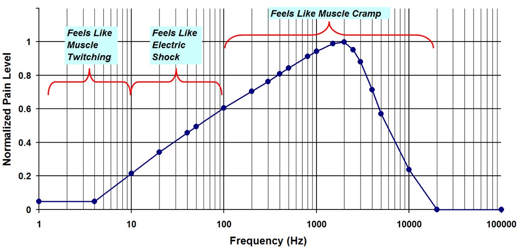
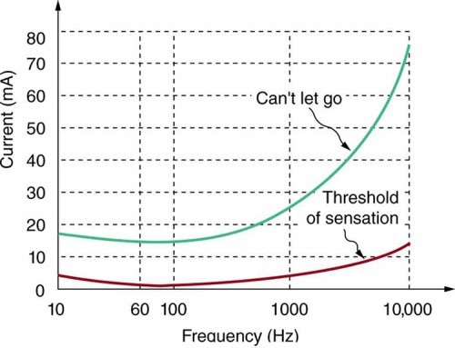
The other (possibly more important question) is how do currents at higher frequencies affect the human body - if I have a device that maybe doesn't trip until over 150mA (at 1kHz) do I still have additional protection? I think I recall that 50 or 60Hz is about the worst possible choice of frequency for shock considerations, but can currents at higher frequencies be safely ignored entirely?
I guess similar considerations might potentially arise anywhere we have power inverters .. so my heat pump might be just the tip of the iceberg,
- Andy.