I think that I am getting to grips with solar PV, but slowly.
Annex D82 shows a typical domestic system. I do not intend to have load shedding, but there will need to be metering of the connection to the grid. Presumably, this is achived by putting a CT clamp on the relevant cable.
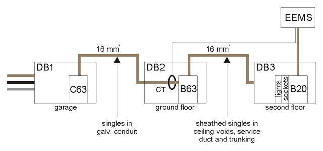
I would like to get the installation as ready as it can be for when I get a system put in. On the second floor, there is a small DB which serves one lighting and one socket circuit. For some reason which is unclear, the distribution circuit uses 16 mm² cable. So the easiest and most economical approach would be to wire the inverter output into the second floor DB as shown in the diagram below.
Whilst I have the floorboards up for other work, I thought that it would be useful to install a CT clamp. So, my question is whether there is a standard design, which would allow me to do so, or whether each manufacturer has their own specifications?
If any of you can see any other potential snags, do please let me know.