This discussion is locked.
You cannot post a reply to this discussion. If you have a question start a new discussion

Parallel MCB with fuses to feed frequency drives

46764c050bc7511d6dcb732a28ff5099-huge-img_0667.jpg

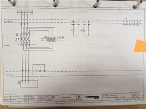
Here you can see the frequency drive is connected to the feed via 50A fuses and in parallel with this is a 0.2A MCB. This then powers the frequency drive.

I think the 0.2A is for a pre stop to the drive and the status signal to the DCS. Could someone explain as I haven't seen this before.

Parents
  • Former Community Member
    0 Former Community Member
    Are L1, L2 & L3 permenantly live?


    It could be a "pre-charge" circuit, ours used to be internal, we would switch out a high resistance just after the 3ph was applied to the drive, to reduce the magnetising current in the inernal RLC filter etc. as inrush current limiting.


Reply
  • Former Community Member
    0 Former Community Member
    Are L1, L2 & L3 permenantly live?


    It could be a "pre-charge" circuit, ours used to be internal, we would switch out a high resistance just after the 3ph was applied to the drive, to reduce the magnetising current in the inernal RLC filter etc. as inrush current limiting.


Children
No Data