This discussion is locked.
You cannot post a reply to this discussion. If you have a question start a new discussion

Sourcing and Sinking PLC I/O using a sensor

Hi I need help as I'm just not getting this..


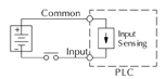
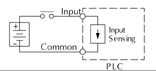
Sinking - Power externally supplied. Current passes through load, then into sensor and then to ground.

Sourcing - Sensor uses supply voltage to pass current. Sensor drives current out, through the load on to ground.


I really can't picture how this works even using google images!

Does sinking have a constant supply and sourcing doesn't?


Sorry it just isn't making sense to me.
Parents
  • Former Community Member
    0 Former Community Member
    Hi Stephen,


    OK, inputs are the same but the opposite way around! ;)


    Now if we use the same analogy of a 24V DC supply system.  Ignore ground/earth, because whilst systems are earthed, it is not for functional reasons so much.

    Please realise that I am using conventional discrete components to explain the way this kind of system works, this is an analogy, rather than a real life system, just for you to grasp the concept, if I am explaining it well enough!


    For a sourcing input card.

    This time the actuator is the external sensor, let's use a limit switch, it could even be a manual on/off switch, as simple as a light switch on the wall.

    The +24V DC goes to the common +ve connection on the input card.

    Simplifying this somewhat, imagine that there is a relay on the input card.

    The +24V will go to the A1 terminal on the relay on the input card.

    The A2 terminal will go to the connection that is the designated input.

    This designated input is then wired out to one terminal of the switch.

    The other side of the switch is then wired to the 24V DC supply -Ve (0V).

    Thus, when the switch is closed current will flow from the +24 through the A1, coil, A2, wiring to switch, through the closed switch, to the 0V (DC-Ve) terminal of the power supply.

    This will allow the relay on the board to close and thus the contacts of this imaginary relay to close and provide a signal internally within the PLC.
    Sourcing PLC Input Module,
    plc input modules


    For a sinking input card.

    Again, the actuator is the external sensor, again, let's use a limit switch, it could even be a manual on/off switch, as simple as a light switch on the wall.

    The +24V DC goes to one side of the switch.

    The other side of the switch is then wired to the input terminal on the PLC card.

    Again, simplifying this somewhat, imagine that there is a relay on the input card.

    The +24V from the card input, will go to the A1 terminal on the relay on the input card.

    The A2 terminal will go to the common -Ve/0V DC connection on the card.

    This common -Ve is then wired back to the -Ve of the 24V DC supply.

    Thus, when the switch is closed current will flow from the +24 through the closed switch contacts the A1, coil, A2, back to the -Ve common of the card, to the 0V (DC-Ve) terminal of the power supply.

    This will allow the relay on the board to close and thus the contacts of this imaginary relay to close and provide a signal internally within the PLC.

    Sinking PLC Input Module
    plc input modules 


    Diagrams above from:
    https://library.automationdirect.com/3-wire-sinking-sourcing-devices-plc-input-modules/


    And, no, I didn't copy the text and concepts from anywhere, it's all from memory, I used to work for a PLC OEM! ;)

    There is some more on sinking and sourcing here:
    https://library.automationdirect.com/sinking-sourcing-concepts/

    I've not checked it's validity though, I would expect it to be reliable and correct.


Reply
  • Former Community Member
    0 Former Community Member
    Hi Stephen,


    OK, inputs are the same but the opposite way around! ;)


    Now if we use the same analogy of a 24V DC supply system.  Ignore ground/earth, because whilst systems are earthed, it is not for functional reasons so much.

    Please realise that I am using conventional discrete components to explain the way this kind of system works, this is an analogy, rather than a real life system, just for you to grasp the concept, if I am explaining it well enough!


    For a sourcing input card.

    This time the actuator is the external sensor, let's use a limit switch, it could even be a manual on/off switch, as simple as a light switch on the wall.

    The +24V DC goes to the common +ve connection on the input card.

    Simplifying this somewhat, imagine that there is a relay on the input card.

    The +24V will go to the A1 terminal on the relay on the input card.

    The A2 terminal will go to the connection that is the designated input.

    This designated input is then wired out to one terminal of the switch.

    The other side of the switch is then wired to the 24V DC supply -Ve (0V).

    Thus, when the switch is closed current will flow from the +24 through the A1, coil, A2, wiring to switch, through the closed switch, to the 0V (DC-Ve) terminal of the power supply.

    This will allow the relay on the board to close and thus the contacts of this imaginary relay to close and provide a signal internally within the PLC.
    Sourcing PLC Input Module,
    plc input modules


    For a sinking input card.

    Again, the actuator is the external sensor, again, let's use a limit switch, it could even be a manual on/off switch, as simple as a light switch on the wall.

    The +24V DC goes to one side of the switch.

    The other side of the switch is then wired to the input terminal on the PLC card.

    Again, simplifying this somewhat, imagine that there is a relay on the input card.

    The +24V from the card input, will go to the A1 terminal on the relay on the input card.

    The A2 terminal will go to the common -Ve/0V DC connection on the card.

    This common -Ve is then wired back to the -Ve of the 24V DC supply.

    Thus, when the switch is closed current will flow from the +24 through the closed switch contacts the A1, coil, A2, back to the -Ve common of the card, to the 0V (DC-Ve) terminal of the power supply.

    This will allow the relay on the board to close and thus the contacts of this imaginary relay to close and provide a signal internally within the PLC.

    Sinking PLC Input Module
    plc input modules 


    Diagrams above from:
    https://library.automationdirect.com/3-wire-sinking-sourcing-devices-plc-input-modules/


    And, no, I didn't copy the text and concepts from anywhere, it's all from memory, I used to work for a PLC OEM! ;)

    There is some more on sinking and sourcing here:
    https://library.automationdirect.com/sinking-sourcing-concepts/

    I've not checked it's validity though, I would expect it to be reliable and correct.


Children
No Data