How is this varistor connected in the unit you have ?
Where are the rectifiers is this a vehicle type situation creating a DC output or an AC output machine with rectifiers on the armature to create the rotating permanent magnet ?
How big is the alternator? (vehicle, small building size generator, power station are all quite different .
Also what kind of load and load step size is expected ?
If it is a voltage limiting device you might expect it to be in parallel with the lines that need protection - but what they are, and why they need such protection without knowing more I cannot tell you.
Varistor connected in parallel across the DC supply which is the output of Rotating rectifire diodes.For details refer the attached AVK alternator drawing.
Alternator is 2660 KVA which is installed in Power plant.
I checked varistor normally its showing open circuit.
Just want know will it protect,
1. Rotating rectifire diodes
2. Main Rotor windings.
from which kind of fault it will protect generator.
I am not familiar with that machine, but I assume this is AC picked up on the rotor, rectified to create a DC, to be the adjustable 'permanent magnet' that rotates inside the main generating stator. That would seem about right for a machine of that size.
So, if that is right...In normal operation, the varistor does not conduct, but
Consider a violent back EMF on the generator output (a load fault or a nearly lightning strike) - at a snapshot in time some of the stator coils are in the position to be transformer coupled into the coil that is this rotating magnet, and depending on the impulse polarity, may be pushing back against the rectifiers but with nowhere to go. Unchecked the voltage at this point may keep rising until the diodes break down, shorting their 3 phase excitation winding.
Far better then to clip the voltage by allowing the varistor to break down at a slightly lower voltage than the diodes - the varistor has a characteristic as per the example curves below and is the basis of the modern surge protector. Once the voltage surge has passed, the varistor stops conducting and the rectifier carries on un-damaged, the AC output recovers within a fraction of a cycle; the lights may flicker a moment but everyone is much happier if they stay on afterwards ?
If the alternator could be guaranteed to only ever drive slowly changing resistive loads, and be nowhere near switching transients or thunderstorms the varistor would not be needed, but in reality it is.
The one in this genset will be probably a very large area one, rated to dissipate some thousands of amps surge for some tens of microseconds, and will be more like the red curve, but with the current calibration in hundreds of amps not A.....
It protects the rectifiers, but also limits the peak voltage that can be induced in the rotating coils so protects them too, when just using more or higher rated diodes would not.
A generator is used to refer to a unit that produces energy, using a different type of energy. For example, in steam engines (in the past steam technology was a dominant technology in industry and in engines), the unit that converts heat energy into steam (steam pressure) is called a "steam generator". Today, the common and common use of the word generator is to describe a unit that utilizes kinetic energy to generate electricity.
An alternator is a private case of a generator. As its name implies, an alternator is a generator whose electrical output is alternating current (AC). It is not clear? Not that it's complicated, just need some background on what electricity is and how it is produced. I will try to explain briefly:
The basis for understanding how electricity is generated lies in a theory that defines the relationship between electricity and magnetism, based on the "Faraday Law". A change of magnetic field drags an electric field, and a change of an electric field drags a magnetic field. That is, electricity and magnetism are considered as two aspects of the same force, the electromagnetic force.
The relationship between electricity and magnetism is formulated in the Maxwell equations, according to which: a conductive wire through which an electric current flows produces a magnetic field that envelops the wire in a circular fashion; A conductive wire loop in which an electric current flows produces a magnetic field similar to a magnetic rod; A variable straight magnetic field produces a rotating electric field. These three "rules" may sound a little strange to those who encounter them for the first time, but two simple conclusions can be drawn from them:
If we create a relative motion between a magnet and a conductive wire so that the magnetic field in which the wire is located changes, we will create an electric current inside the wire. This is the principle that enables electricity generation. 2. Using an electric current a magnetic field can be created. This is the principle behind the mechanism of action of an electric motor.
Generation of electricity in a simple generator is based on the creation of a relatively circular motion between a magnet and the coils of a conductive wire. In light of this, in half of each rotation the change in the magnetic field is polar north to south, and in the other half of the rotation the change is back from a south pole to north. The direction of change in the magnetic field that the coils "feel" has an effect on the direction of the electric current generated in them. For this reason, the default of the electrical output of a generator based on rotational motion, is an alternating current that varies according to the sine of the cutting angle of the wire and the magnetic field; Or in other words an electric current that changes its direction in each half cycle of rotation.
Scheme of the principle of operation of the alternator: A magnet located between conductive wires rotates on its axis so that the magnetic field in which the wires are located changes and an electric current is created in them. The source of the chart is from Wikipedia.
When we use the battery as a power source, we get a current supply (Direct Current = DC) - which runs continuously in the same direction. You can read more about the characteristics of alternating current, the advantages and uses of the types of currents, the geometric relationship between the direction of the magnetic field and the direction of the electric current, and a good explanation in English about direct current and alternating current.
Although even at IEC power stations the generators are alternators, in common parlance "alternator" is commonly used to refer to the electric current generator in a car. The alternator in the car receives kinetic energy from the engine by a belt that connects the engine shaft to the alternator shaft. The alternating current generated is "aligned" by a diode system so that it can charge the car's battery, which in turn provides direct current to all car systems.
What you post is true, but is not an answer to the original question. The OP has now told us that this is a full sized alternator of 2.7megawatts, not a baby one in a car for a kilowatt or so, and the rectifiers are rotating, to avoid the need for exciter slip rings and brushes.
Varying the Vdc allows the magnet strength to be adjusted to separate the functions of voltage control and rotation rate.
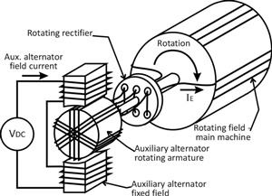
A noddy diagram to illustrate what is under discussion is reproduced below, the main generation occurs in the stator not show around the armature of the mains machine.
The attraction is that there are no high current paths that involve moving contacts, so no brushes to wear etc.
Exciter field winding have some permanent magnet poles which give initially excitation to exciter armature winding to generate residual voltage in Stator winding. Once the AVR sensed residual voltage via PT secondary winding(In case 11KV Generator) then AVR start increase excitation till the alternator terminal voltage reach upto nominal voltage.
Initial the AVR give DC output to Exciter field winding & then exciter armature winding induce AC voltage(as per Faraday Law), then AC three phase voltage pass via Rotating rectifire diode assembly & covert AC to DC, which is further feed to Rotor field winding. Here Varistor is connected across the +ve & -ve supply which is feeding to rotor main winding from Diodes.
As per data available on internet the Varistor protect the electronic component from Transient Voltage or surge in voltage or lightning strike. in these condition the varistor internal resistance become low & it create close path which will protect the components.
But i am not understand that normally Back EMF is using in motors but in generator there is no any Back EMF generated. How the voltage will increase in Excitation system?
The impulse that will damage the rectifier is short duration , very short compared to the cycles of 50 or 60Hz AC you are generating.
For the whole of the duration of the dangerous pulse voltage, the the generator does not move very far, and it can be considered to be static (not rotating). (Think like a flash photo freezes the action ? Its not really frozen, but it looks as if it is.)
Now if you just have coils in a more or less fixed orientation, that is a transformer, albeit one with a funny shape.So the pulse coming in from the load side ends up being transformed into a pulse on the diode side of the rotor winding..
The Back EMF in a motor is the generator voltage - so the supply only needs to provide the difference.
However, I am thinking of the very short duration back EMF you get when you switch off a current in an inductive circuit.