This discussion has been locked.
You can no longer post new replies to this discussion. If you have a question you can start a new discussion

530kW motor checks? !!

Former Community Member
Hello to all, and I do hope that people can advise me on this?


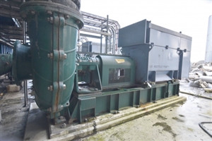
Firstly: what checks can I best do for a possible purchase of a single ABB - AMB 630 LC16 ABA C 530kW pump unit, which is unable to be properly tested (powered up) as the plant it was operating in has been decommissioned, and is currently being scrapped.


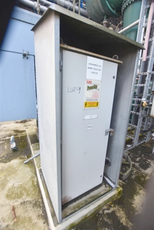
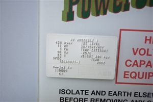
The unit appears to be mostly self contained, with a separate 'powercap' capacitor cabinet.

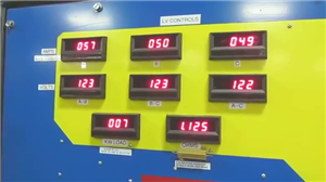
There are 8 in total, in various conditions and all look like this:
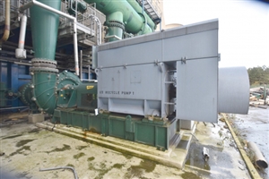
200fe3153df9ce950ab8d3220e14538c-huge-1.jpg
b9f52bfa5dd0afd26e92e2d1d4f97d2c-huge-2.jpg
9b08e6def31b626893d8d9e9b05b139f-huge-3.jpg
acf1cd9e473f756f328529e5cb2fc6d0-huge-4.jpg


Secondly: No switching gear is 'included', however I could always ask the company (who's pulling the site apart) if it's possible to obtain the original starter systems maybe???

But would this be a good idea, considering again it's in an unknown condition.


From the 8 available, I've selected 2 that appear to be the most suitable for hopefully reusing again (not bashed about, leaking oil etc) and thus generally look ok, so possibly from that can choose the final one.... but it would be great to know how best to maybe pick the best from any testing that could be done where they stand now, without any power.


Obviously with big industrial machine as this, it's not your average consumer second-hand electrical goods....

....that one just plugs in, and then hopes it works when power is applied!


(Thanks in advance to any replies)
Parents
  • Former Community Member
    0 Former Community Member
    The TigerTek motor test indeed was very impressive.

    Certainly a great bit of kit they had!


    Interesting though that on 120v each phase is drawing almost roughly the same current A57, B50, C49.
    3499cbc36a94497c930923319faa867e-original-vlcsnap-2021-03-17-21h22m12s515.png

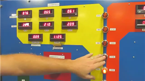
    Stepping up to 208v it's A76, B65, C61 so again virtually the same on each phase....
    5a5ce03b265805d69db05465b4af4be5-original-vlcsnap-2021-03-17-21h22m33s046.png

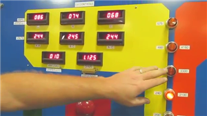
    At 240v however it then begins to alter ?? A86, B74, C68
    5db9b27f67a2f532b1154e2cafb51f52-original-vlcsnap-2021-03-17-21h23m05s156.png

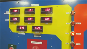
    At 380v it's..... A134, B121, C103
    8d594124425c80be94957511dd765c03-original-vlcsnap-2021-03-17-21h23m21s062.png

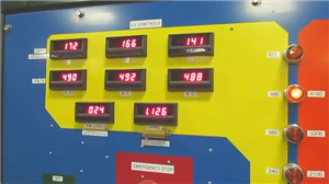
    At 480v, A172, B166, and C141
    a7ab6592e796eb6af7ae3f193aa04e51-original-vlcsnap-2021-03-17-21h23m40s093.png

    All voltages are almost the same, BUT phase C's current draw seems way lower compared to A.

    Does anyone possibly know why A was pulling far more current, than C?

    Is that normal??

    It seemed odd to me, A taking mostly the highest load current.

    That would mean A is loading far more than the others which could result in a premature failure.

    I thought the whole point of 3 phase was that each phase loaded equally, which thus providing a balanced power loading?

    ?


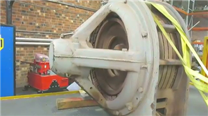
    Also, yes - if there had been a catastrophic failure of a bearing, or a fanblade breakage...

    Certainly that high inertia in the rotor, would not have been held by those straps!
    8701ce258c51d42be93ccb23b2458a43-original-vlcsnap-2021-03-17-21h24m43s203.png

    I don't know how much that motor weighed, but having that stall and then fly across any workshop wouldn't be a good outcome ?


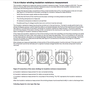
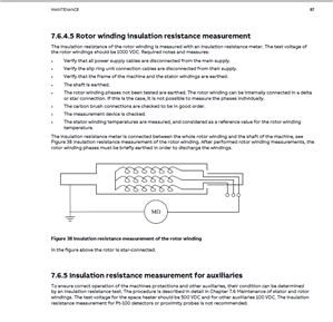
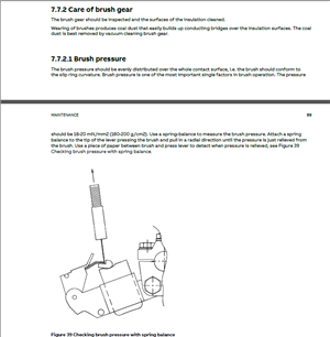
    ABB have been superb, and sent over a superb PDF motor manual which gives tons of info, here are a few screenshots of stator and rotor winding checks, and also brush pressure.
    f44a2d575afefede9099520e16a5ed4f-original-stator_winding_resistance_checks.png
    54dbe7e49910df27179cd8a8532f9a1c-original-rotor_winding_resistance_checks.png
    e8f4f6b2fc4956c34027ed8a25f4a329-original-brush_pressure.png


    It does also mention anti-condensation heaters and temperature sensors too.


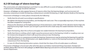
    Additionally it mentions oil leakage and the possible causes!

    bcc37a479e8f8a4f28a107158bc779f1-original-oil_leakage.png

    Certainly a superb manual.

    Warman have also been super, and sent a PDF of their pump ?


    I have no idea as to how the motors were disconnected, if the power station engineer did that or it was done by the demolition company.

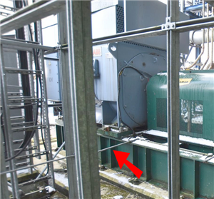
    Worryingly, lot 9 shows a small conduit feed intact:
    65f04d0b5dd5a961839430c1c4afd116-original-lot09.png

    Possibly a sensor line or some low voltage feed, anti-condensation or temp control maybe.


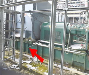
    However lot 10's conduit has been sheared off......
    04cabf66381242d1bcbfd852dbc083bc-original-lot10.png

    The motor's frame bolts have also been undone.


    Look closely again at these two pictures.... and both shows other cable lines cut.


    It would appear that (maybe) most have been 'pruned' with no regard for the reinstallation of the machine.

    If it was a feed into the actual plant then sobeit, but if just to a nearby controller box or sub-unit then the entire cable (or cables) will all have to be replaced (at extra cost), when they could have been simply disconnected carefully from one side and easily reconnected again at the new site.


    Could also be a major problem if associated equipment and/or panels/boxes are removed or even lost.

    It may not be possible to easily reinstall things properly!


    Looking rather a mess... and it seems reading the manual the cooler unit (topbox) was delivered separately on any initial motor installation, so possibly that should come off before the motor is even lifted out.


    The entire motor (as it sits on the concrete pad) wasn't designed to be craned out in one go.

    Hopefully someone doesn't attempt this, or the base frame could get badly bent.....

    Worse... one of the eyebolts breaks from an overload

    OR the cooler is pulled apart from the motor, and the motor then drops to the ground.


    The new site location for any motor purchased would yes have to have a suitable supply, but I was trying to get a motor, (or motors) just saved from any damage really.

    Getting them out certainly from the demolition area..... before being wrecked beyond any use.


    I do though wonder, if they haven't already been, or will be??

    Doesn't look good.
Reply
  • Former Community Member
    0 Former Community Member
    The TigerTek motor test indeed was very impressive.

    Certainly a great bit of kit they had!


    Interesting though that on 120v each phase is drawing almost roughly the same current A57, B50, C49.
    3499cbc36a94497c930923319faa867e-original-vlcsnap-2021-03-17-21h22m12s515.png

    Stepping up to 208v it's A76, B65, C61 so again virtually the same on each phase....
    5a5ce03b265805d69db05465b4af4be5-original-vlcsnap-2021-03-17-21h22m33s046.png

    At 240v however it then begins to alter ?? A86, B74, C68
    5db9b27f67a2f532b1154e2cafb51f52-original-vlcsnap-2021-03-17-21h23m05s156.png

    At 380v it's..... A134, B121, C103
    8d594124425c80be94957511dd765c03-original-vlcsnap-2021-03-17-21h23m21s062.png

    At 480v, A172, B166, and C141
    a7ab6592e796eb6af7ae3f193aa04e51-original-vlcsnap-2021-03-17-21h23m40s093.png

    All voltages are almost the same, BUT phase C's current draw seems way lower compared to A.

    Does anyone possibly know why A was pulling far more current, than C?

    Is that normal??

    It seemed odd to me, A taking mostly the highest load current.

    That would mean A is loading far more than the others which could result in a premature failure.

    I thought the whole point of 3 phase was that each phase loaded equally, which thus providing a balanced power loading?

    ?


    Also, yes - if there had been a catastrophic failure of a bearing, or a fanblade breakage...

    Certainly that high inertia in the rotor, would not have been held by those straps!
    8701ce258c51d42be93ccb23b2458a43-original-vlcsnap-2021-03-17-21h24m43s203.png

    I don't know how much that motor weighed, but having that stall and then fly across any workshop wouldn't be a good outcome ?


    ABB have been superb, and sent over a superb PDF motor manual which gives tons of info, here are a few screenshots of stator and rotor winding checks, and also brush pressure.
    f44a2d575afefede9099520e16a5ed4f-original-stator_winding_resistance_checks.png
    54dbe7e49910df27179cd8a8532f9a1c-original-rotor_winding_resistance_checks.png
    e8f4f6b2fc4956c34027ed8a25f4a329-original-brush_pressure.png


    It does also mention anti-condensation heaters and temperature sensors too.


    Additionally it mentions oil leakage and the possible causes!

    bcc37a479e8f8a4f28a107158bc779f1-original-oil_leakage.png

    Certainly a superb manual.

    Warman have also been super, and sent a PDF of their pump ?


    I have no idea as to how the motors were disconnected, if the power station engineer did that or it was done by the demolition company.

    Worryingly, lot 9 shows a small conduit feed intact:
    65f04d0b5dd5a961839430c1c4afd116-original-lot09.png

    Possibly a sensor line or some low voltage feed, anti-condensation or temp control maybe.


    However lot 10's conduit has been sheared off......
    04cabf66381242d1bcbfd852dbc083bc-original-lot10.png

    The motor's frame bolts have also been undone.


    Look closely again at these two pictures.... and both shows other cable lines cut.


    It would appear that (maybe) most have been 'pruned' with no regard for the reinstallation of the machine.

    If it was a feed into the actual plant then sobeit, but if just to a nearby controller box or sub-unit then the entire cable (or cables) will all have to be replaced (at extra cost), when they could have been simply disconnected carefully from one side and easily reconnected again at the new site.


    Could also be a major problem if associated equipment and/or panels/boxes are removed or even lost.

    It may not be possible to easily reinstall things properly!


    Looking rather a mess... and it seems reading the manual the cooler unit (topbox) was delivered separately on any initial motor installation, so possibly that should come off before the motor is even lifted out.


    The entire motor (as it sits on the concrete pad) wasn't designed to be craned out in one go.

    Hopefully someone doesn't attempt this, or the base frame could get badly bent.....

    Worse... one of the eyebolts breaks from an overload

    OR the cooler is pulled apart from the motor, and the motor then drops to the ground.


    The new site location for any motor purchased would yes have to have a suitable supply, but I was trying to get a motor, (or motors) just saved from any damage really.

    Getting them out certainly from the demolition area..... before being wrecked beyond any use.


    I do though wonder, if they haven't already been, or will be??

    Doesn't look good.
Children
No Data