This discussion has been locked.
You can no longer post new replies to this discussion. If you have a question you can start a new discussion

Answers Please. Electrical Technology.

1. A load of 2.5kW takes a current of 12 Amp from a 230 Volt supply. Calculate the power factor.


2. Three single phase loads are to be connected to a three phase supply. All at unity power factor. The loads are,


i, 60 Amp.


ii, 50 Amp.


iii, 40 Amp.


By any method determine the neutral current.


Z.
  • As a foot note - Mike, you do have the correct angle,  although I prefer 330 degrees (anti-clockwise rotating phasors).

     How do you edit these posts!


    Regards

    Geoff Blackwell
  • You wait ages for a Blackwell posting then three turn up at one go.

    Welcome back Geoff lad.

    Nice to see you
  • Zoomup:

    1. A load of 2.5kW takes a current of 12 Amp from a 230 Volt supply. Calculate the power factor.


    ANSWER: P.F. = 2500/230 X 12.


                                 = 0.906


    2. Three single phase loads are to be connected to a three phase supply. All at unity power factor. The loads are,


    i, 60 Amp.


    ii, 50 Amp.


    iii, 40 Amp.


    By any method determine the neutral current.


    ANSWER = 16.5 Amps.


    Answers & questions supplied from a City & Guilds and I.E.T. joint publication.


    Z.


  • Well  City & Guilds and the I.E.T. joint publication have not produced an accurate answer then.  I don't know what method they have used but  a 'proper' calculation produces the result that I, and others,  gave (Mike's answer would have been the same but for a simple arithmetic error).


    A decent phasor diagram would also come close to the correct answer.

    BTW I got my angle wrong in my earlier post?

    Regards

    Geoff Blackwell

  • My method:


    In = I1+ I2 + I3 where all terms are phasor quantities


    In polar form


    60 @ 0 degrees + 50 @ 120 degrees + 40 @ 240 degrees


    In rectangular form (you can obtain this using the Polar to Rectangular function on a calculator or trigonometry)


    by calculator function


    I1 = 60 + j0

    I2 = -25 + j43.3

    I3 = -20 - j34.64


    collecting terms

    Re    Img

    60    0

    -25    43.3

    -20    -34.64


    15  + j8.66


    in polar form (by calculator)


    17.32A @ 30 degrees


    Which by the way proves that I got my angle wrong in my earlier post.


    Regards

    Geoff Blackwell
  • let down by failure to use the book of tables , I knew the new fangled calculator was a mistake ?.

    Mind you it seems C and G have a similar problem.


    To edit your own posts click on the 3 spots on the high right hand side in the post listing.  And then as courtesy add an 'edit' note if the change is more than cosmetic to avoid confusion to those who have already read it.


    to do crossing out, like this in the editor change to source edit, and add strike and /strike inside <> signs around the offending section. And then copy and save all the text  somewhere , as swapping back from source view to normal view before posting sometimes crashes for reasons not clear to me.


    I'll be back with the PEN lift voltage tonight, work is calling...

    regards

    Mike.
  • Thanks Mike


    On the angle question I originally obtained my answer using a program I wrote some years ago that includes a facility to calculate the parameters of a broken neutral fault (as it stands, just for unity power factor).  This gave me my 330 º.  This is, in fact, correct for a positive phase sequence i.e: L1 @ 0 º, L2 @ 240 º, L3 @ 120 º - anticlockwise rotation which is the normal system in use.


    30 º comes from a negative sequence.


    Regards

    Geoff Blackwell

  • Agree 330E  =30 W and all that - but in my defence,  the original question did not specify rotation.

    Of course if it had, I'd have had a 50% chance of getting that wrong as well...

    Looking at your workings, they are elegant and general, but I must admit while I fully understand complex no.s and use them for work I find to couch explanations as magnitude and angles them more visual in some way - I like to actually close my eyes and see the cogs rotating in the mathematical model, and imagine the electrons as rushing around, rather than just crunching the numbers (it also greatly increases my accuracy - the chance of spotting an error is increased by knowing from the visualisation roughly what sort of size and direction  the answer ought to  be.. Without that my chances of being off by  pi, or two or -1  or j increase rapidly with the no. of steps in the calculation).  (not good enough for spotting 17 instead of 20 something though)

    It does get some funny looks when I do this at work, and refer to 'gear ratios' and 'missing teeth' when comparing harmonic frequencies and phases in complicated systems though.

    M.
  • As promised, neutral offset voltage with open PEN.


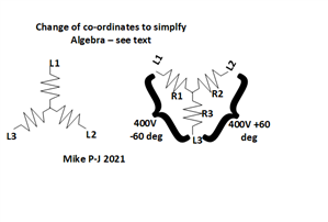
    3 loads  R1= 230/60 ohms  R2 =230/50 ohms and R3 = 230/40 ohms.


    Let us ground the 40A phase (call it L3 )and consider L1 and L2 to be two phases of 400V relative to it, one at 60 degrees phase offset relative to the other.

    We can transform our voltages back to a 'centre earth' at the end, and I prefer to work with only 2 moving parts in the model.


    V 3 is the drop across the R3 resistor due to the sum of the two currents coming in through R1 and R2. They are not orthogonal and cannot simply be superposed, so we calc current in R3 from V1 with V2 grounded, then current in R3 from V2with V1 grounded, then

    do the in phase and orthogonal thing to get the magnitude and angles.


    see figure below

    08bdd61293a5b04ad2554607fb0f934a-original-neutral_offset.png


  • Thanks Mike

    My software considers a broken neutral with all the phases intact.


    I used Millman's theorem to calculate the various voltages and currents.  In this example it is not too dramatic as the loads are not too far out of balance (worst case voltage is Vbs ( voltage between blue phase and the star point of the transformer - blue phase whats that!) = 254V @ 123º.  Hardly destructive but this is usually a dynamic system so things could go pear shaped.


    The voltage between the transformer star point and the neutral on the consumers side of the break Vsn =27v @ 330º.  So well below the 70 V maximum for EV systems.


    Regards

    Geoff Blackwell