This discussion is locked.
You cannot post a reply to this discussion. If you have a question start a new discussion

Diverted Neutral Current

So for the past 5 years if so I have been seeing and experienced a phenomena known as diverted neutral current or diverted networks current.

It has a few names. Much like the incredibly slow realisation that type AC RCDs have had their day. Even though type A has been about over twenty years.

I get at least two / three messages a week from electricians who are now using clamp meters to check the earth conductors of LV installations. Low and behold they find anything from 2A up to 169A in a few cases.

I have research this at work for the last few years and some of the work I have ensured is published via the following link.

http://tangle-tamers.com/page21.html

We have also managed to produce a visual guide for measuring this issue. This work also helped with the Broken PEN IET article. 

It appears the aged life expired state of the LV network is a bigger problem and will only continue to grow. The use of CNE cable has been a tad o IMO. Years ago the RECs admitted cost was the key factor, but made the decision based upon a REC. a government owned network. Since privatisation the DNOs have fixed on fail, leaving the LV side unmonitored to a large extent. This is now slowly changing. But we assume a broken PEN conductor or failure of this can cause hazardous over voltages but also large amounts of network currents bypassing the broken PEN and importing and exporting on domestic earthing in some cases.

whilst the number are small in the scheme or things. It’s a growing issue. The network know about it. But the industry appears to not be discussing it. Why do we not get a safety alert for all electricians nationally. If we find this why are the DNOs and yes some are taking horrific decisions. And in some cases charging. I’ve issued a safety alert for the Railway where I work. 

be good to gauge folks thoughts as a broken pen gives you CNE consideration in a home, not allowed by BS 7671 and also brings up the whole what is safe isolation with this in mind. We never consider earth as a energised conductor and only ever consider rise of voltage. Maybe with changing and ageing networks, non linear loads etc. We need to change the way we see things.

I live in hope the networks will be more open on this.

thoughts..

Parents
  • Agree with Graham - a truly 'isolating' transformer that also introduces a ground break is a hard thing to organise, without either compromising the ADS on one side or the other, or bringing metalworks at the primary and secondary side grounds potentials rather closer together than is comfortable.

    Clearly a fault primary to core requires the core to be on the PME earth  or there is no ADS for that fault, and yet one side of the secondary winding needs to be earthed to the load side ground as well, to make a TNS  so the the secondary side ADS work properly. So somehow you need the core and the secondary to be 6 feet apart.  Or more realistically you have some zone where the two earths are adjacent but treated as 'potentially live' in the presence of each other, but this involves locked doors/ cabinets and a level of faff.

    (*) I ignore small transformers of split bobbin construction that allow double insulation- you can do this for a few hundred watts, but at higher powers the losses due to the imperfect magnetic coupling are not really acceptable.

    In most cases an in-line RCD in an insulated enclosure and some gapping of SWA armours etc is a far easier thing to manage and less likely to be accidentally compromised.

    As both L and N downstream of the RCD should be treated as live, and neither ever come near earth except during fault, the diverted neutral problem is removed and so in the transformer ;-)

    You do need RCDs you can trust though, not the grey import specials that do not actually trip...

    Mike.

  • As a bit of a sidetrack there are places that really do need transformers with core, primary and secondary windings really well insulated from each other but they are only seen in the world of pulse power or high RF , and those customers do not worry about magnetic losses, or indeed safety of personnel, to the same degree (no one is there when it is fired up, and even if they are, they are certainly not there to comment after it has fired ..)

    Pulse power.

    (Tall thin core about the size of a stocky door frame.)

    That cone shaped secondary has earth at the bottom, and so can be near the core, and winds up to a classified no of kV at the top, hence the greater spacing. Note also the top rolled edges to reduce discharges, and the inter-winding structures to 'grade' the field . It would normally sit in oil .

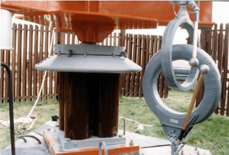
    RF isolation

    ('Austin rings') low frequency AC for aircraft warning lights etc.

    Here the air gapped loops are a transformer, the lower one  iron cored and wound toroidally in the normal way and the upper loop is the secondary, wound hula hoop-like on an insulating former.
    These are used to get a 'mains' supply onto a tower that is a vertical antenna, but also happens to be driven with a few KV p-p of RF at the base insulator...

    Neither approach is remotely  practical compared to  a conventional transformer or simply  an RCD and a gap..

    Mike

Reply
  • As a bit of a sidetrack there are places that really do need transformers with core, primary and secondary windings really well insulated from each other but they are only seen in the world of pulse power or high RF , and those customers do not worry about magnetic losses, or indeed safety of personnel, to the same degree (no one is there when it is fired up, and even if they are, they are certainly not there to comment after it has fired ..)

    Pulse power.

    (Tall thin core about the size of a stocky door frame.)

    That cone shaped secondary has earth at the bottom, and so can be near the core, and winds up to a classified no of kV at the top, hence the greater spacing. Note also the top rolled edges to reduce discharges, and the inter-winding structures to 'grade' the field . It would normally sit in oil .

    RF isolation

    ('Austin rings') low frequency AC for aircraft warning lights etc.

    Here the air gapped loops are a transformer, the lower one  iron cored and wound toroidally in the normal way and the upper loop is the secondary, wound hula hoop-like on an insulating former.
    These are used to get a 'mains' supply onto a tower that is a vertical antenna, but also happens to be driven with a few KV p-p of RF at the base insulator...

    Neither approach is remotely  practical compared to  a conventional transformer or simply  an RCD and a gap..

    Mike

Children
No Data