This discussion is locked.
You cannot post a reply to this discussion. If you have a question start a new discussion

What is the use of Capacitor & Varistor connected in parallel between DC negative & Ground(PE) & DC positive & Ground(PE)

Dear Team Members, 

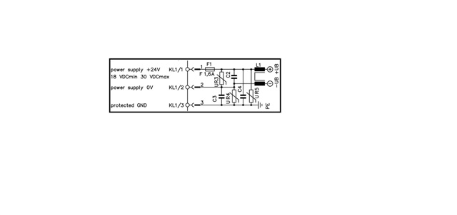
I have one smoke detector(Input power supply 24VDC) which having following below connections & Pl see the attached drawing also...

1. C3 Capacitor & UR4 Varistor connected across the DC 0V & GND... 

2. Varistor UR3 & C2 Capacitor across DC +24V & 0V....I think this C2 & UR3 will protect against overvoltage....PL comment if its right..

3. C4 Capacitor & UR5 Varistor connected across DC+24V & GND..

We have one 24VDC power distribution & monitoring module...this module detecting the DC Positive & negative earth fault in distribution side(Setting is 3KOhm)...so smoke detector getting 24VDC from this power distribution module..so when we connecting power to smoke detector then the power distribution detecting DC Negative earth fault...

n connection no. 1 i am getting 118 ohm resistance between DC 0V terminal & GND & When checked C3 capacitor its showing open... no any capacitance value showing..i think because of this getting DC Negative earth fault. 

can somebody explain that what is the use of Capacitor & Varistor in connection no. 1,2 & 3. 

Pl see the below smoke detector power supply connection. 
  • Basically there are two things going on - the triangle of capacitances are to suppress high frequencies at any amplitude - so if for a microsecond or so an amp is induced in say the loop between ground and positive- perhaps due to a sudden magnetic shock from switching in an adjacent circuit, instead of the peak voltage between  the lines rising rapidly, the capacitor starts to charge, and the voltage still rises but now at a rate set by the current divided by the capacitance - in effect the maximum slew rate has been limited, or if you prefer, the high frequency , faster component of the waveform edge is removed. For very high frequencies we talk about the 3 lines being effectively connected together - this is sloppy, they are sort of connected, but by an impedance that falls with increasing frequency.

    Now the varistor - in normal operation these do nothing, but will conduct if the voltage across them becomes too much (if you have a part no. we can look up how much.) This is to clamp the voltages that can appear between the lines, so that the electronics further down is not subjected to an over-voltage event.

    So between the two,, the expensive and delicate electronics should see greatly reduced voltage spikes and only with slower changing rise and fall times than if the protection was not present.

    This will greatly reduce the risk of malfunction when the wiring is run along side things that are potential sources of interference, such as cables feeding  switch-mode devices, motors controlled by VFDs and so on.

    In some locations it will not be needed, but in others it will be exercisied every day and it is cheaper to fit it than to find out after the accident that  you really should have.

    Mike.