Hived off from the electrical section.
Pitch believed to be 1.5mm.
Z
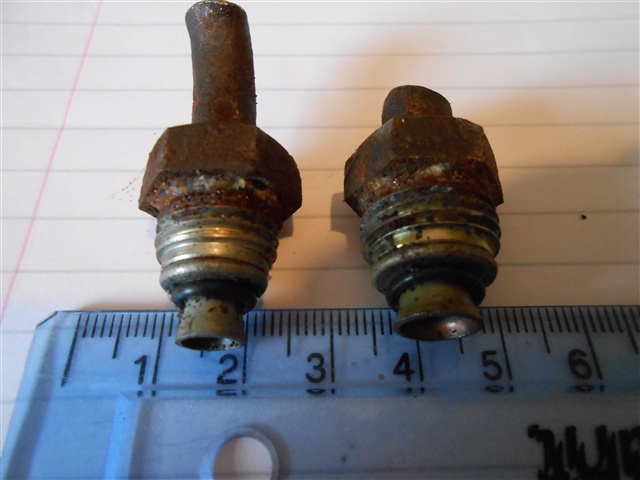
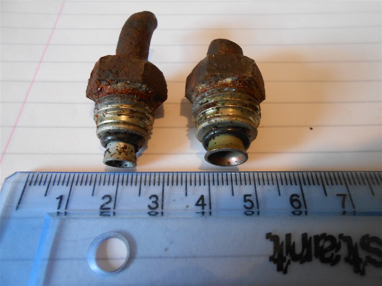
Pictures. I had to saw through the pipes to get a socket onto the fittings to get them to turn for removal. They were rusted onto the steel pipes
Hived off from the electrical section.
Pitch believed to be 1.5mm.
Z
Pictures. I had to saw through the pipes to get a socket onto the fittings to get them to turn for removal. They were rusted onto the steel pipes
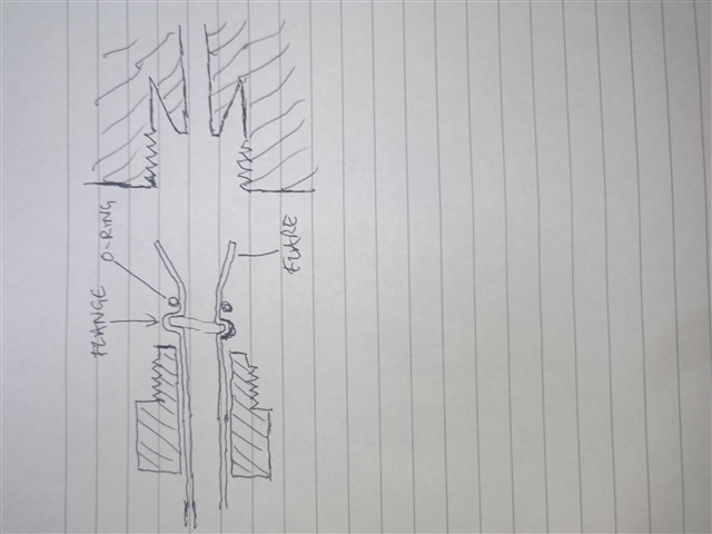
I had wondered about the flare at the end of the tubes, but this is one that I have not seen before, including the O-rings. If new tube nuts were made: (1) how would the new flare be made; and (2) how would the new pipes be joined to the old?
So is that just a very short steel bolt of the right thread with a plain hole though it , perhaps conically cupped to retain the O ring, and then a flare on the pipe end to retain the O ring from the other side.?
To be fair if so you can probably remove the rust with a mild acid pickle - try kilrock ? (or others sear by citric acid or vinegar or cold stewed tea overnight - the pros needing speed use dilute hydrochloric acid but it's a bit of a faff for a couple of small parts at home ) and re-use. The hard part then will be getting the right flare angle on the new pipe ends.
If they need to be remade, then how sure are you of the 1.5mm thread pitch? was that with a thread gauge? - could it be 16TPI which is close enough to 1.5mm to get a couple of turns and then jam. Also need the OD to the nearest 0.1mm or so, and the profile (metric are 60 degree Vee normally but 55 and 47 are seen in other standards.)
Mike
if you can rescue the flared pipe tails, it may at a push be possible to sleeve braze or silver solder a plain cylinder to connect to a new pipe - sort of like a plumbers capillary fitting I fear that if not then a flaring cap tool will need to be made- the profile will need to be copied well enough to seal the O-ring maybe 200um. Nitryl O ring? M.
The fact that the flares are of different diameters suggests that the flaring occurred when the fittings were tightened in situ.
The pipes also seem to have rounded flanges on them just above the o-rings, like the pipe was deformed to create them, a bit like this
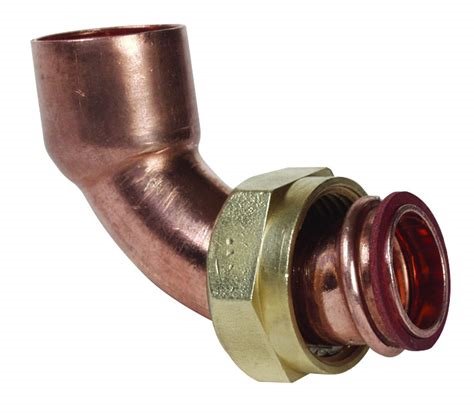
yep that is the sort of thing you would need to acquire or make for the right pipe size, but in a typical flare plumbing fitting, small errors in the pipe profile are corrected - squeezed out of it - by the compression of the fitting as the tube is trapped between 2 bits of metal. Here you seem to have a rubber or nitryl O-ring, bearing on one side of the flare, so it will not provide the force to correct any error in the trumpet angles, and will leak.
However this is conjecture - a description of which surfaces form the high pressure seal(s) would help. and ideally a dimensioned drawing will reveal all.
M.

That's not quite how I would flare brake or fuel pipes, or even a power steering pipe.
Please may we see a picture of the holes into which the pipes are inserted? Useful also to know what is on the other end of the pipes (or do you just want to bypass the cooler?) and something about the vehicle.
We're about to take you to the IET registration website. Don't worry though, you'll be sent straight back to the community after completing the registration.
Continue to the IET registration site