This discussion has been locked.
You can no longer post new replies to this discussion. If you have a question you can start a new discussion

I don't have a lathe . . .

. . but I do have an ancient compact tractor!

The power steering ram is connected to the steering arm with the usual ball coupling but with a straight M12 bolt rather than the tapered bolt that you generally find on track rod ends.

Unfortunately the M12 hole in the steering arm has become ovalled causing excessive play.

The steering arm is part of the casting for the front hub and 4WD system and cannot be removed so any repair will have to be in situ.

My first thoughts were to try and drill out and then ream the oval to 18mm and insert a new 12mm id bush but I was wondering if the collective brains on here had a better solution.

Thanks. G

  • I think being a tight fit so that the bush does not spin in the enlarged hole nor the bolt shank move inside the bush will be more important - what you really do not want is the bolt threads moving and chewing up the non-moving joints. The only part that should both pivot and rock is the lubricated and hopefully hardened ball within the joint - and it ought to be able to accommodate  alignment errors of a few degrees and full rotation about the hole axis but you can verify its safe wobble range will be enough by testing it in advance with a long spike or a chunk of studding.

    Mike

  • Thank you for your replies. So, are you saying Mike that I could, in effect, bolt a stud into the steering arm with a nut top and bottom so that it is rigid, immobile and then secure the rose joint with, maybe, an R clip?

    If so, what I really want is some sort of stud that is smooth, hardened at one end and M12 threaded on the other.

    I'd be grateful if you could keep applying your minds to this!!

  • So am I looking for something like this?

    What on earth do I google?

  • No, but you could have an over-sized stepped bolt inserted from below.

    Sorry, I forgot, you don't have a lathe. Wink

    Forget nuts top and bottom and R-clips. The inner part of the rose joint needs to be firmly clamped to the steering arm in such a way that nothing will come loose.

  • Well that didn't upload. Try this.

  • R-clips have their uses, but mostly so that things may be disassembled readily, or in place of a split pin.

  • Sorry Chris, I don't quite understand what you're saying. Can't insert a stepped bolt from below as the steering tie rod is in the way. I thought I had it clear in my head but surely the rose joint should be "floating"

  • The ball of the 'rose' joint is the only moving part, and it moves within the body of the rose joint. The pintle should not rotate within the ball nor within the steering arm (hence my comment about tack welds in the field.). 

    This is surprisingly hard to explain in words. Sketch coming, but not quickly.

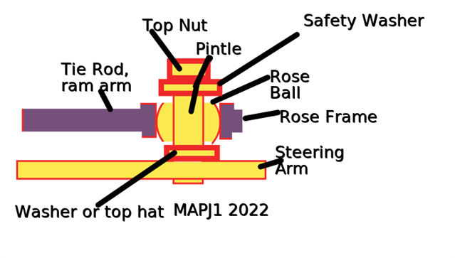
    EDIT sketch 1, the naming of the beast. lower washer or top hat sets rose ball height and means ram arm comes in level and un-strained.  safety washer ensures steering action not totally lost if ball ever pops from frame. All yellow parts move as one. Unless ram arm miles off parallel so optimum ball height varies during turn and then a rising pintle is needed.

    Mike.

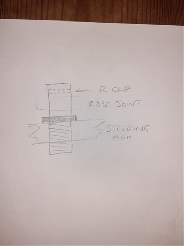
  • Thank you very much Mike, your "sketch" is somewhat better than my pencil drawing on the back of an invoice! And I think I have finally got my thick head around it. I've ordered a new bush so I'll mic it up when it's been in the freezer and drill appropriately!

    Next problem, I suspect the clutch is slipping!

    I'll report back just in case anyone is remotely interested!

    Thanks again for you help, I had completely misunderstood how the rose joint worked.

  • That is good,  - as we so often find on here the battle is getting 'the obvious' out of one head into another, and without a pic, and even sometimes with one,  it is easy to run off with the wrong end of the stick - I have lost count of the times I have commented with an answer to not quite right for the question that was actually intended. 

    Be aware that mechanical language is a bit regional, so  my words and what folk call the bits may not match at your local motor factors or whatever. 
    I should have said - if the motion of the ram end and the steering arm is not co-planar, (and if it isn't then the ram mechanism may jam), then the place to let it rise and fall is  on the pintle in the hole of the rose joint ball . If you do need that then that will need to be lubricated, as it will also tend to turn there as well as at the ball in the frame. Looking at your photos more closely, the hole in the rose joint ball does look like it may be lined - if that is an oiling bronze bush, then it is intended to allow that use, but of course not on a thread, but a smooth hardened surface.

    Mike.