Using resettable fuses in place of single use - what make or break system to create??

Hi all, 

So I'm doing some testing and part of it requires checking what happens when certain pins are open circuit, shorted to gnd and shorted to 12v right ?

historically this was done with single use fuses (2a) but I want to use something resettable

So I've identified one tthat trips on 0.5A and has a withstand lf 100A, but how or what do I use for a make break indicator??

In line led I don't think I'd see quick enough, a potential divider then an arduino to read the analogue voltage maybe?

  1. Struggling with this one
Parents
  • Once the 'fuse' is in its high z 'blown' state, then there will be a significant voltage across it.  will this be enough to operate an  opto isolator? , or will the current leaking round through that that do damage to what the 'fuse' is protecting. something like a 4n35 in series with a K or 2...

    If you have a ground reference common to the DUT and the measurement, perhaps just a MOS FET  and some high value resistors?

    Mike.

  • Ahhhhh because its gone open circuit the current will drop to 0 and the voltage will spike, 

    I hadn't considered optos yet 

    I'd gone down the line of led, which won't switch on long enough I imagine to shine before it blows, and some kind of arduino solsolution.

    Will the open circuit voltage be measurable or just infinitely high. I was wondering if I could use an analog read function on an arduino to see it's either at 12v or higher, then set it to just report blown or not blown based on this value. The worry I had was the common ground reference just shunting the current through the resistor chain keeping the circuit active when I need it to trip. 

  • I had imagined the LED part of the opto, with some k ohms in series with it, across the fuse. Given the high CTR and low dark current of a modern opto coupler you only need send a few 10s of uA down the LED path. And you can improve both by cooling.
    When there is a voltage, LED lights, and the fuse has popped. Or two, one each side of the fuse, relative to gnd.  If both the on, fuse OK.

    If you want to capture the transient then you need a scope probe on each side.

  • Right okay, sorry for the delay. 

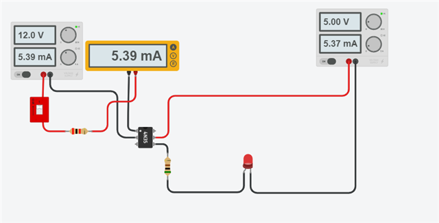
    So something like this? The Switch is acting as the fuse, and the resistor after it, is limiting the current to the IR LED for the opto, then the opto can either be ran off a 5V USB source (to connect to a laptop) meaning the 12V system is isolated from that side of things :) ?

  • I mean, that works but will I see the LED for the time the fuse is open. 

    I was thinking is the next step some kind of latch to enable the 5V LED line to be permanently illuminated until the power is removed? Maybe I'm overthinking this. 

Reply Children
  • Wait. I had a brainwave 

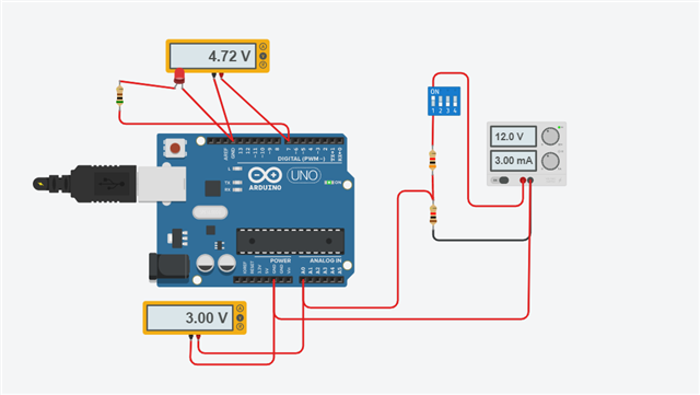
    I made it customisable. the 12V comes in and the dip switch is acting as a fuse here as there's no fuse in tinkercad. 

    The software is watching the ADC value on pin A0 and if it's equal to or greater than 614 (which is the ADC value for 3V, which is the output from the potential divider to signify 12V supply, then the LED is lit. 

    It switches off when the fuse blows, I'm just about to reverse the software though so it's on when it's blown to give a better indicator.