Using resettable fuses in place of single use - what make or break system to create??

Hi all, 

So I'm doing some testing and part of it requires checking what happens when certain pins are open circuit, shorted to gnd and shorted to 12v right ?

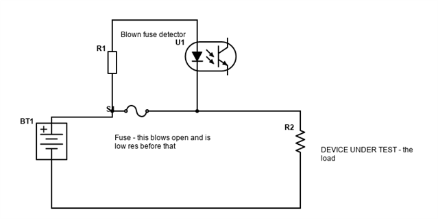
historically this was done with single use fuses (2a) but I want to use something resettable

So I've identified one tthat trips on 0.5A and has a withstand lf 100A, but how or what do I use for a make break indicator??

In line led I don't think I'd see quick enough, a potential divider then an arduino to read the analogue voltage maybe?

  1. Struggling with this one
Parents
  • OK. Now I'm confused...

    I had imagined you had a a fuse in series with a load (device under test), the two in series across a 12V supply, such that when the fuse blows the DUT loses its supply and wanted to know if the fuse was blown. Clearly it is more complex than that.


    So what do you need to do exactly ?
    ps circuit drawn on https://www.digikey.co.uk/schemeit/project/# and exported as png - they have fuses...

    Mike

Reply
  • OK. Now I'm confused...

    I had imagined you had a a fuse in series with a load (device under test), the two in series across a 12V supply, such that when the fuse blows the DUT loses its supply and wanted to know if the fuse was blown. Clearly it is more complex than that.


    So what do you need to do exactly ?
    ps circuit drawn on https://www.digikey.co.uk/schemeit/project/# and exported as png - they have fuses...

    Mike

Children
  • Thanks for the link Mike, that is a really quick and easy way to draw circuits, not seen it before. I added a few embellishments to yours (latch):-

  • oops

  • Hey mike, it's for an ecu, so there's a break out board which allows us to bridge the pins on the ECU and apply open circuit, short etc. 

    We're doing OC , short to ground, short to ignition and short to perm live. 

    The issue is we're using a 20cm or so loom which is literally an inline 2A fuse, so one end is connected to the pin being tested and the other is connected to ground or the ign or perm live. 

    Fuse blows instantly which is expected but it's another one to throw in the bin. 

    What I've done with the arduino is put the fuse in line with a potential divider which i can read off an analog input pin, this way I can trigger status LEDs which are ran from a 5V supply (from a laptop USB for example), meaning I can have one lit to say the 5V is OK, and the other to come on when the ADC readout on the analog input moves from one state to another. 

    This seems a workable solution to me, but I may have either missed something or made it overcomplicated :)! 

    ADC wise it's just set to pick up either a 3V signal (the potential divider gives that out), or < 3V. 

    I'm still tweaking code but essentially it's gonna either flash when the 12V is applied or when it's lost. 

    Lost seems more useful. 

  • did you actually want to emulate the fuse action with something else, and save binning a stack of fuses ? It is also possible to replace the fuse with a low value resistor and use it to fire a circuit that opens the supply more or less the manner of a fuse/ breaker. It is more involved, but I am happy to advise how in slow time.

    Or you could use a poly-fuse, but they do not go completely 'off' and trickle some mA  in the hot state.

    Mike