Amtech ProDesign Transformer Fault Conditions

Evening All, 

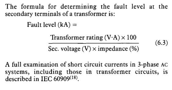
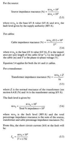
Does anyone know the calculation method Amtech ProDesign uses to calculate the Line Fault and Earth Fault levels? 

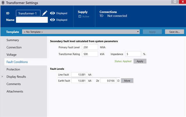
Based on the following secondary fault level conditions

Primary Fault Level: 250 MVA

Transformer Rating : 500 kVA

Impedance: 5%

The software will provide the following fault conditions 

Line Fault: 13.881 kA

Earth Fault: 13.881 kV 

Ze: 0.0166 Ohm

I believe I have an idea of how the Line Fault is calculated but I'm slightly stumped at how the Earth Fault and Ze are obtained and why it is the same as the Line Fault. 


Parents
  • Well, lets crunch a few numbers and see how close we get ;-) I will use easy numbers to illustrate so please forgive the 250V in place of 230 etc.

    a 500kVA tx giving 250V L-N  open circuit per phase would be 666A full load on any one phase (imagine a star of 3 loads wired L-N  we have 500 000 watts to split equally between them, so each load gets a third each )

    Now at full load (666A) the voltage will droop 5% 250/20 = 12.5 volts .

    So, on a dead short (we can think of that as a 100% voltage drop ) L-N or L-E we might expect 20 times that current 

    That is 2 * 6660 amps.   That would be  120+1200+12000 amps = 13320 amps - the same as you S/W given my slack handfuls rounding.

    Zs drops out of that sum.

    Note that an  L-L-L fault could be as much as about twice that,  as the effect of the 3 phases is to more or less remove the half of the volt drops associated with the neutral - call it an upper bound of  27kA ..

     I have ignored the voltage drop on the HV side, as it  is small  - I think the other Tx s on the same HV feed will scarcely blink for the short time that this one makes the buzz of death while it blows its (400A or 800A) output fuses, but to be sure we should estimate to  see by how much.

    Fault level 250MVA - transformed down to our 250V is  equivalent to a PSSC of 1 million amps, split across 3 phases, so 330kA per phase - about 20 times less limiting effect than the effect of the transformer internals. So other users will see a 5% drop on the HV while the TX cooks into a dead short.

    Except that the TX will probably be star delta wired, and so a fault on one phase LV pulls 2 phases on the HV, but the conclusion, that it is OK to pretend the HV droop does not reduce the fault current a fat lot, remains. So lets just pretend the HV supply is 'stiff' in the face of faults of that magnitude and save a load of aggro.

    Does this agree your thinking ?

    Mike.

    PS you may find this Western power doc STANDARD TECHNIQUE : TP4B/2 Relating to 11kV and 6.6kV Transformer Protection a source of some relevance to this sort of case.

  • Hi,

    Thanks for the detailed reply. I was hoping for the formulae that the software was using but I will check out the document you have referenced. The basic formula I am familiar with to determine the L-L short circuit fault is current is 


    However, this gives a value of 14.433 kA rather than 13.811 kA within my original post. 

  • well, that formula you quote is essentially my method condensed onto one line rejigged  a bit, and also calculates for a single phase L-N or L-E fault ignoring the primary side HV voltage drop effect, (which will only change things in the third significant figure).

    I cannot see  the off-load secondary voltage you assumed to get to to get 14,433 but it must have been 230 or so - the SW should be deducing the open circuit (off load) voltage to be 5% higher than the on load rated voltage or the transformer - which is reasonable.

    The only folk who can say for sure what the SW does are the chaps/chapesses who wrote it  - you could do worse than drop them a line, but I cannot imagine a response will be that quick.. 

    Mike

Reply
  • well, that formula you quote is essentially my method condensed onto one line rejigged  a bit, and also calculates for a single phase L-N or L-E fault ignoring the primary side HV voltage drop effect, (which will only change things in the third significant figure).

    I cannot see  the off-load secondary voltage you assumed to get to to get 14,433 but it must have been 230 or so - the SW should be deducing the open circuit (off load) voltage to be 5% higher than the on load rated voltage or the transformer - which is reasonable.

    The only folk who can say for sure what the SW does are the chaps/chapesses who wrote it  - you could do worse than drop them a line, but I cannot imagine a response will be that quick.. 

    Mike

Children