Earth Fault operated in 11KV Solid BUS when made close loop.

Dear All,

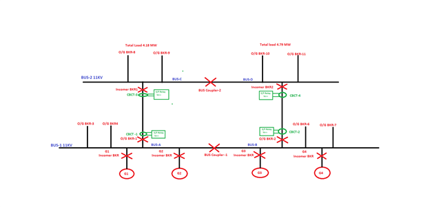
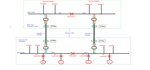
We have two 11KV BUS's BUS 1 & 2, In BUS-1 there are two sections BUS-A & B. Same two sections BUS C & D are there in BUS-2. 

In BUS 1 the BUS coupler is always closed position(for closing using synchroscope) & BUS-2, BUS coupler keeping always Open condition. BUS-2 getting power through BUS C incomer BKR 1 & BUS-D from Incomer BKR2.

Since the BUS coupler-1 is closed position & as per i understand the voltage at BUS-C & BUS-D should be same. Also we verified the voltage across BUS coupler -2 with HV sticks, there were no any voltage difference found. 

In this scenario the BUS coupler -2 can closed without synchronization, i think that's why we don't have synchroscope installed on this BUS coupler-2.  

when we tried to close BUS Coupler-2 with following conditions,

1. BUS Coupler -1 Close position. 

2. O/G BKR-1 & Incomer BKR-1 Close position.

3. O/G BKR-2 & Incomer BKR-2 Close position.

when we were closed BUS Coupler -2 same time following BKR's tripped on Earth fault,

1. O/G BKR-1 & Incomer BKR-1 Close position.

2.O/G BKR-2 & Incomer BKR-2 Close position.

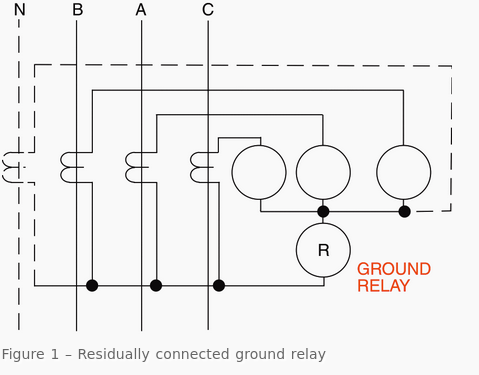
For earth fault protection for O/G & I/C BKR 1 & 2 cables are equipped with CB C.T(Core balancing).  CB CT ratio is 50/1 & settings is 7.50 Amp with 500 ms. 

Running load on BUS-C is 4.18 MW & BUS-D is 4.79 MW. I don't think this difference of active power can cause of this issue. 

Please find the attached SLD of our switchgear. Kindly please go through the above case & share your valuable comments. 

Parents
  • I'm inclined to agree. But please correct me if what follows is not correct.

    I presume all genset are happily running in parallel both before and after the trip, and the bus coupler 1 remains unchanged. So we can siimplify the 4 g3eneratrs and the coupler and the A-B bus, and say this is just a single supply, feeding two outbound lines BK1  BK1, with breakers at both ends.

    These 2 lines have current transformers that operate the breakers, if the current in the 3 phases sum to anything more than 7,5 amps. (in perfect world, they would sum to zero, regardless of the load, resistive or reactive. )

    This is fine when line 1 is supplying one load, and line 2 is supplying another.

    But as soon as the coupler 2  makes contact - nothing  stops current flowing down one phase line of BK1, but coming back up the other phases via BK2? Now the two current transformers both see an imbalance, though there is no fault - except that the parallel supplies do not quite divide the current in the same ratio on all 3 phases.

    Now if either of coupler 2 or coupler 1 was no present this imbalance could not arise.

    If you do intend to run the system with both bus couplers in the closed (connected) state then you need to arrange the current transformers so that  all six phase currents are summed - this will be near zero !

    Regards

    Mike.

  • Dear Sir,

    Thanks for your valuable comments. 

    All BKR's are keeping in ON position except BUS Coupler 2 which is in OFF position always. 

    All engines are running in load sharing mode which share the load equally. Isochronous load sharing mode.  

    Please see the attached SLD where CBCT location has mentioned. 

    But as soon as the coupler 2  makes contact - nothing  stops current flowing down one phase line of BK1, but coming back up the other phases via BK2? Now the two current transformers both see an imbalance, though there is no fault - except that the parallel supplies do not quite divide the current in the same ratio on all 3 phases.

    I could not understand well the comment above. Please elaborate bit on this comment.  

    I don't think is there any circulation current flowing after close of Bus coupler2 ..which normally happened in close of parallel transformers but in our case its Slid Bus. 

    could you please share some details, how to do arrangement of CBCT so that this situation of earth fault via CBCT can avoided. 

    Looking forward for your valuable comment. 

  • Apologies if I was not clear. I will try again, and do ask again if it still does not make sense.

    The updated diagram shows the current transformers are as I thought, thank you .

    imagine that coupler 2 is open.

    The wires passing through CBCT1 for example carry a current that sums to zero - if current goes down one phase wire and through the load, it must come back up the other phases - unless there is a fault there is no alternative path.

    so breaker1 does not trip . (we could imagine each phase current to be 100A but the vector sum of the current transformers is still zero.)

    The same applied to CBCT2 of course, by symmetry. (and let us imagine another 100A load, just for easy sums on that side too)

    Ah but now the problem,..

    Let us close the second bus coupler, so now the load current can split unevenly between the left and right paths, and imagine our 100 amps per phase on each side but with the worst possible imbalance.

    Imagining  on phase 1 that all of the combined 200A for the two loads goes through the CT on the left , and the 200 Amps for the other two phases passes via the other CT on the right.
    both CTs now see an imbalance, but the left and right hand  loads still see 100 per phase each, and the gensets see the same load.

    Can you see why the thing trips in that situation without a real fault ?

    Of course such a horrible imbalance as one phase fully diverted is not likely once switches have finished closing, as the current will share in the ratio of the wiring resistances in the two paths - which will  be similar, but never  identical.

    So if say the parallel paths shared  the current flow 60/40 on one phase but 50/50 on another and 45/55 on the third phase, the kind of number that is quite possible, above some critical load level the tripping problem is the same, just harder to see.

    If you are still struggling - come back again and we can re-word this another way or I can try a diagram.

    Mike

  • Dear Sir,

    Thanks for sent the detailed reply.

    It would be good if you can share some kind of the diagram, then it will be more helpful to start working in direction to resolve the issue. 

    Is there any way forward to resolve this false sensing of CBCT so that after close of BUS Coupler2 CBCT's can see the real Amps load on each phases of both sides. 

    Once again thanks for your valuable comments, they gave me now new direction of thinking about the behavior of such faults. 

Reply
  • Dear Sir,

    Thanks for sent the detailed reply.

    It would be good if you can share some kind of the diagram, then it will be more helpful to start working in direction to resolve the issue. 

    Is there any way forward to resolve this false sensing of CBCT so that after close of BUS Coupler2 CBCT's can see the real Amps load on each phases of both sides. 

    Once again thanks for your valuable comments, they gave me now new direction of thinking about the behavior of such faults. 

Children
  • I'll need to find the time to draw something for you, but basically once the bus coupler is closed, the decision to trip BK1 or BK2 is no longer independent, - the sensing and the tripping decision must be combined and the readings of the current transformers must be summed to reach that decision.

    (I must say it makes life harder - why is the earth fault detection on these lines and not sensing on the outbound lines to the loads ?)

    I presume you really have 3 current transformers at each breaker and the secondary windings are either in series or parallel to create the signal to operate the trips - can you advise which ? it  will help if the picture is correct !

    Mike.

  • The diagram below is for parallel wired CT systems and shows a primary with 3 phases and  a distributed neutral but if (like the UK ) there is no neutral at HV,in your locale, then ignore the dotted  wire.

    When 2 such lines are driving a load in parallel then the signal to the two ground fault relays would need to be paralleled as well.

    An alternative way to look at this is (pic from this website https://electrical-engineering-portal.com/ground-fault-protective-schemes )

    Remember that, while voltages combine in series, currents combine in parallel.

    The 3 meters (which can be omitted and replaced by short circuits) show the individual phase currents, but the fault relay only sees the out of balance term,

    When interlocking the two breakers, one could wire the pairs of phase  CT windings for corresponding phases from the 2 branches in parallel to give a total current reading for each phase prior to combination.

    Mike.

  • Dear Sir,

    Thanks for sharing the requested diagram. 

    I presume you really have 3 current transformers at each breaker and the secondary windings are either in series or parallel to create the signal to operate the trips - can you advise which ? it  will help if the picture is correct !

    Only one per breaker Core balancing CT has been using which carry 3Phase 3 core MV cable from his iron core & CBCT secondary is connected to Earth fault relay. Pl find the attached updated SLD. 

    I think you were in perception that three different CT are using to make the earth fault detection on each side of line(Left & right). 

    Between these two switchgear sections, the distance is around 1KM. 

    Kindly please go through attached updated SLD & share your valuable comments.