
***Note this is a working piece of work and would like some feed back and other peoples insights into this******
Introduction:
As the electrical landscape transforms by integrating advanced systems like heat pumps, solar photovoltaic (PV) panels, and battery storage solutions, professionals face new challenges in ensuring system safety and reliability.
While inverters, central to these technologies, introduce high switching frequencies, it's pivotal to understand that these frequencies can interfere with the accuracy of essential tools like current clamp meters.
Especially when testing for diverted neutral currents, it's crucial to consider how high-frequency components might impair the meter's precision. This paper dives deep into these nuances, emphasising the need for appropriate tools and practices to ensure accuracy in our rapidly evolving electrical environment.
Background:
Current clamp meters are a cornerstone of an electrician's toolkit. By harnessing the principles of electromagnetic induction, they offer a non-intrusive method to measure the current flow, turning the magnetic fields around conductors into quantifiable current readings. However, as the complexity of electrical systems and appliances increases, so do the challenges in getting accurate readings, especially when dealing with harmonics, which can impair the meter's accuracies.
Example Scenario
Picture this: John, an experienced electrician, arrives at a newly renovated property. The property boasts an array of contemporary equipment: a state-of-the-art air source heat pump (ASHP), a solar photovoltaic (PV) system, and a modern battery storage system. Each of these devices employs inverters that operate at high switching frequencies.
John's task for the day is to test for potential diverted neutral currents. He starts his procedure by clamping onto the main earthing conductor using his trusty clamp meter - a tool that had served him well over the years. However, as he observes the readings, they appear unusually high. Confused by the results, John retests several times, only to find consistently inconsistent results.
Given the readings, he feels there might be a significant issue with diverted neutral currents, potentially endangering the property's electrical system. He considers advising the property owner to take drastic measures, like a comprehensive system overhaul or engaging the Distribution Network Operator.
Unbeknownst to John, the high-frequency inverters from the ASHP, PV system, and battery storage interfered with his clamp meter readings. The actual state of diverted neutral currents at the property differed entirely from what his instrument indicated.
Had John made decisions based solely on these readings, the property owner might have incurred unnecessary costs and hassle. Such scenarios underscore the crucial importance of understanding the complexities of modern electrical equipment and the potential pitfalls of relying solely on traditional testing methods without considering the impact of high-frequency devices.
Harmonic Currents:
Harmonic currents are commonly understood as integer multiples of a primary system's frequency. For instance, with a foundational frequency of 50Hz, typical examples would be the 2nd harmonic at 100Hz, the 3rd at 150Hz, and so forth.
However, it's vital to note that while this is a conventional representation in real-world scenarios, especially with advanced electrical equipment and non-linear loads, harmonics may not strictly adhere to this pattern. Devices like electronics, fluorescent lighting, and inverters can introduce irregularities. These non-linear loads disrupt the straightforward relationship between voltage and current, producing harmonics that may not always be perfect multiples of the fundamental frequency.
Example Calculation:
Suppose a device draws a current with a fundamental frequency of 10A at 50Hz and a third harmonic (150Hz) of 2A. The RMS value of the total current, taking into account the harmonic, can be calculated as:
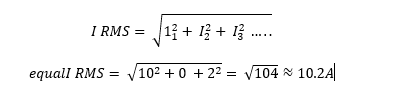
This means the presence of the 2A third harmonic increases the effective current by 0.2A.
Diverted Neutral Currents:
Diverted neutral currents refer to those currents that take an alternate route instead of returning through the designed neutral pathway. This can occur due to interconnected neutral and ground pathways or faults in the system.
These diverted currents can lead to unexpected readings on a clamp meter if they pass through the clamp's loop. For example, if an electrician is measuring the current on a neutral wire, they might expect zero current if all devices are off.
However, if a diverted neutral current flows, the meter could read this unexpected current, leading to confusion or misdiagnosis.
Aim of the Paper:
Where technological advancements are permeating every household – from solar PV systems to air source heat pumps (ASHP) – the electrical landscape has become considerably more complex. Consequently, the tools used to diagnose, measure, and manage this evolving network must keep pace and be impeccably accurate to ensure utmost safety. This paper highlights a critical aspect often overlooked: the precise measurement of electrical parameters, even in high switching frequencies, potentially reaching or exceeding 10kHz.
The objectives are:
Raising Awareness: By exploring the nuances of current clamp meter performances, especially when faced with harmonics and diverted neutral currents, this paper aims to bring forth the urgency of addressing the measurement disparities observed across the industry. Professionals must be not only aware of these challenges but are also equipped to tackle them.
First-Hand Experience: On real-world observations where renowned clamp meters displayed deviations of up to 50% in earth leakage measurements, we will delve into the safety implications of such mismeasurements, especially when they arise due to harmonic interference or diverted neutral currents.
Equipment Suitability: This paper underscores scenarios like domestic properties equipped with modern energy systems to emphasise the importance of selecting the right tool for the job. With the likelihood of encountering high switching frequencies, professionals must ensure that the bandwidth of their clamp meters is apt for capturing accurate readings.
Best Practices and Recommendations: Our endeavour will culminate in proposing robust guidelines for industry professionals. This framework will ensure that despite the challenges posed by harmonics and diverted neutral currents; the industry remains steadfast in its commitment to accuracy and, more importantly, safety.
Diving Deeper into the Importance of Accuracy in Current Clamp Meters in Light of Guidance Note 3:
Guidance Note 3, provided by The Institution of Engineering and Technology, accentuates the criticality of accurate measurements, particularly in earth leakage current clamp meters. The document offers a step-by-step method for inspecting and detecting diverted neutral currents, which can introduce safety risks in electrical installations. Let's elaborate further on the mentioned aspects:
- Earth Leakage Current Clamp Meter:
An earth leakage current clamp meter, as illustrated in Figure C1 of Guidance Note 3, gives a non-invasive means to assess the insulation state of a circuit by evaluating 'earth leakage'. This technique requires the meter's clamp to encircle the live conductors exclusively.
Example:
In smaller installations, a few milliamps of reading might indicate protective conductor currents. However, significantly higher readings could be symptomatic of faults such as line-to-earth or neutral-to-earth, leading to potential safety hazards.
- Diverted Neutral Currents & Dangers:
Diverted neutral currents pose a significant danger, especially when there's a break in the PEN (Protective Earth and Neutral) conductor within the distribution network. Such scenarios can precipitate hazardous touch voltages on the protective earthing system. These touch voltages can be found on exposed-conductive parts, circuit protective conductors, main earthing terminals, and extraneous-conductive parts.
Installations at risk encompass those with PME (Protective Multiple Earthing) conditions, particularly those emanating from public distribution networks, and installations sharing extraneous conductive parts with PME-linked setups.
- Testing for Diverted Neutral Currents:
While there isn't a silver bullet test for diverted neutral currents, Guidance Note 3 stipulates certain checks with tools like non-contact voltage testers, voltage indicators, and earth leakage current clamp ammeters.
Example:
For a dwelling, some actions involve:
- Measuring current in the Main earthing conductor before isolation using a current clamp meter.
- After securing isolation, recheck for current in the Main earthing conductor.
- Assessing voltage presence at various points, such as the main earthing terminal.
Compared with expected outcomes, the results can point towards potential issues related to diverted neutral currents or broken PEN conductors. For instance, large currents in earthing or bonding conductors or unexpected voltage presence post-isolation are significant red flags.
- Implications of Inaccurate Meter Readings:
If your clamp meter doesn't provide accurate readings, especially in the light of complexities introduced by harmonics and diverted neutral currents, then:
Safety Risks: False negatives could give technicians a misleading sense of safety, potentially leading to hazardous conditions. Conversely, false positives can cause unnecessary concerns and interruptions.
Diagnostic Errors: Inaccurate readings can lead to misdiagnoses, causing professionals to overlook genuine or troubleshoot non-existent problems.
Economic Costs: Misdiagnoses might lead to unnecessary replacements or repairs or extended downtimes.
In conclusion, the emphasis on accurate, current clamp meter readings, as highlighted by Guidance Note 3, isn't merely an academic pursuit. It's a pivotal requirement for ensuring safety and reliable operations within electrical systems. As electrical systems evolve in complexity, the demand for accurate, reliable, and agile diagnostic tools becomes even more pronounced.
How True RMS meters work and how harmonics can affect their measurements:
- Differentiating True RMS from Average Responding Meters:
Understanding RMS: "Root Mean Square" (RMS) represents a waveform's practical value or magnitude. For a sinusoidal waveform, the RMS value is calculated as:
True RMS = ![]()
Where Vpeak - is the peak voltage of the sine wave.
Average Responding Meters: These meters measure the average value of the waveform and then multiply it by a factor (typically 1.11 for a sinusoidal waveform) to estimate the RMS value. They are most accurate for pure sinusoidal waveforms and can give misleading results for waveforms with harmonics.
Which to Choose? For environments with predominantly sinusoidal waveforms, average responding meters are sufficient. However, True RMS meters are preferred where non-linear loads are typical due to their accuracy with distorted waveforms.
- Recognising Fundamental Frequency and Its Harmonics:
What's Fundamental?: For UK-based power systems, the standard fundamental frequency is 50Hz.
Harmonics Explained: Harmonics are whole number multiples of this primary frequency. For example, the second harmonic (also known as the first overtone) of a 50Hz system is 100Hz, the third is (50Hz x 3) 150Hz, the fourth is (50Hz x 4) 200Hz etc.……
- Harmonics: The Cause and The Effect:
Origination of Harmonics: Non-linear electrical equipment like rectifiers, variable frequency drives, ASHP, EVc, Solar PV Inverters, etc., draw non-sinusoidal currents. These non-sinusoidal currents give birth to harmonics.
Impact on Waveform: These harmonics, when superimposed on the fundamental waveform, can distort it, shifting it away from a pure sine wave.
Understanding the True RMS Meter's Boundaries in the Harmonics Realm:
Bandwidth Concerns: All meters have a frequency bandwidth that defines the range of frequencies they can measure accurately. If the harmonics are beyond this range, the meter might underestimate or overlook them.
Crest Factor: It’s the ratio between the peak and RMS value of a waveform:
Crest Factor = ![]()
Meters are designed to handle up to a specific crest factor. Highly distorted waveforms, rich in harmonics, can exceed this, leading to inaccuracies.
Sampling Rate for Digital Meters: A digital RMS meter captures several snapshots (samples) of the waveform in a single cycle. A higher sampling rate captures the waveform more accurately. However, if this rate is insufficient, specific high-frequency harmonics might not be adequately recorded, resulting in aliasing.
Accuracy Drop: While a meter might promise accuracy for readings around 50Hz, it might not be as precise for the harmonics, especially those of higher order.
Section Conclusion:
While True RMS meters provide a significant edge in environments with distorted waveforms, it's crucial to acknowledge their inherent limitations. These meters might not deliver the precision we expect in areas with high-frequency switching appliances or when encountering environments dense in harmonics.
Harmonics, especially those of higher order, can challenge the meter's bandwidth, sampling rate, and accuracy. As such, resorting to more advanced and specialised testing equipment is often necessary for precise measurements in these technical scenarios. Relying solely on the standard clamp tester in a technician's tool bag might prove insufficient and sometimes misleading. Always be aware of the environment and choose the right tool for the job to ensure the safety and reliability of electrical systems.
When measuring high-frequency harmonics up to 20 kHz, you'll want to look for meters designed to capture high-frequency content. Power-quality analysers and oscilloscopes are particularly well-suited for this purpose.
Power Quality Analysers: These specialised instruments can measure various power disturbances, including harmonics, transients, flickers, and more. When purchasing or selecting a power quality analyser:
Check the frequency range in the specifications.
Look for analysers that conform to relevant standards like IEC 61000-4-7, which deals with harmonic measurements.
Brands like Fluke, Tektronix, and Dranetz often have power-quality analysers capable of measuring high-frequency harmonics.
Oscilloscopes: For capturing high-frequency events, oscilloscopes are invaluable. While they are primarily used for waveform visualisation, they can also measure and analyse high-frequency content:
Digital oscilloscopes typically have a wide bandwidth, often exceeding 100 MHz or even 1 GHz, making them more than capable of capturing harmonics up to 20 kHz.
Modern oscilloscopes often include Fourier Transform features, which allow you to break down a waveform into its frequency components (harmonics).
Look for scopes with high sampling rates (to capture the waveform accurately) and adequate memory depth (to capture longer waveform durations).
Current Clamp Meters Review
The TIS 570 clamp meter's provided information doesn't mention any specific susceptibility to harmonics in the AC voltage and current measurements. However, a few things can be inferred:
Accurate RMS Measurement: The meter mentions using True RMS for its AC voltage and current measurements. True RMS meters are designed to give accurate readings of sinusoidal and non-sinusoidal waveforms. This means that even in the presence of harmonics, which would cause non-sinusoidal waveforms, a True RMS meter should accurately measure the practical value of the waveform.
Frequency Range for AC Voltage: The accuracy for the AC voltage measurement is specified for frequencies between 40Hz and 1kHz. Harmonics are typically integer multiples of the fundamental frequency (for power systems, the fundamental frequency is usually either 50Hz or 60Hz). Thus, this meter seems designed to provide accurate measurements up to the 20th harmonic (if 50Hz is considered the fundamental frequency). Beyond that, accuracy might decrease.
Frequency Range for AC Current: The accuracy for AC measurement is mentioned for 50-60Hz. This doesn't indicate the meter's performance with harmonics present in the current waveform.
Potential Concerns: Without explicit mention in the specifications, it's hard to determine how much the presence of harmonics might affect the output accuracy of this meter. Harmonics can introduce measurement errors, especially in instruments not designed to handle them.
In conclusion, while the TIS 570 clamp meter provides True RMS measurements, which should be more accurate in harmonics than an average-responding meter, the specific susceptibility or resilience to harmonics is not directly mentioned. If precise measurement in a high-harmonic environment is critical, it would be wise to contact the manufacturer directly or refer to more detailed product documentation.
From the provided information on the Megger DCM305E Earth Leakage Clamp Meter:
The Megger DCM305E features True RMS measurement for its AC functionalities, focusing primarily on detecting earth leakage currents, which tend to be low magnitude. Although True RMS measurement provides enhanced accuracy for non-sinusoidal waveforms, the meter's specifications don't directly address its performance when encountering harmonics.
A True RMS measurement approach allows precise readings of both sinusoidal and non-sinusoidal waveforms. Thus, a meter with this capability should accurately capture the effects of harmonics leading to non-sinusoidal outputs. However, the accuracy's frequency range remains crucial in determining its efficacy in harmonic management.
In power systems like those in the UK, harmonics manifest as integer multiples of the foundational frequency of 50Hz. If the Megger DCM305E's accuracy is solely pinned to a 50Hz range, its performance might waver when faced with higher-order harmonics.
The provided specifications of the Megger DCM305E don't elaborate on its frequency response or precision in high-harmonic scenarios. Therefore, while the in-built True RMS feature implies a certain level of robustness against harmonics, there isn't a definitive mention of its prowess in such environments.
Summarise and compare the Megger DCM305E and the TIS 570 clamp meters based on the information provided, as well as discuss their potential susceptibility to harmonics:
- Megger DCM305E Clamp Meter:
Features & Functions:
Measures AC current up to 100 A.
Earth leakage clamp meter.
Measures AC voltage up to 600 V.
True RMS reading.
Jaw size of 40 mm.
Frequency response of 40 Hz to 400 Hz for AC current and voltage.
Harmonic Impact on Megger DCM305E:
Given its frequency response of 40 Hz to 400 Hz, the Megger DCM305E is optimised for measurements in the standard power frequency range and may not be accurate for higher frequencies. This means harmonics, especially those beyond 400 Hz, might not be captured effectively, which could affect the readings' accuracy. The True RMS capability ensures it will read sinusoidal and non-sinusoidal waveforms accurately within its specified frequency range.
- TIS 570 Clamp Meter:
Features & Functions:
Measures AC and DC current and voltage.
Maximum reading of 5000 counts.
True RMS reading for AC measurements.
Maximum jaw opening of 23 mm.
Measures resistance and continuity.
Digital display with four digits.
AAA batteries power it.
Frequency response of 40 Hz to 1 kHz for AC voltage and 50-60Hz for AC current.
Harmonic Impact on TIS 570:
The TIS 570 has a broader frequency response for AC voltage measurements, up to 1 KHz, making it more suitable for capturing higher-order harmonics than the Megger DCM305E. For AC current, its frequency response is limited to the standard power frequency range, similar to the Megger model. Its True RMS capability ensures accuracy for sinusoidal and non-sinusoidal waveforms within the specified frequency range.
TIS 570 & Megger DCM305E Comparison:
Range & Functionality: The TIS 570 provides a broader range of functionalities, including DC and resistance measurements. The Megger DCM305E is more specialised for earth leakage current measurements.
Size & Form Factor: The Megger DCM305E has a more prominent jaw size, which might help clamp around more oversized conductors. The TIS 570 is more compact.
Frequency Response: The TIS 570 has a broader frequency response for AC voltage measurements, potentially making it more sensitive to higher-order harmonics in voltage readings. For current tasks, both meters have a similar frequency response.
Harmonics Susceptibility: Both meters are True RMS and will accurately measure non-sinusoidal waveforms within their frequency response range. However, their accuracy can decline when subjected to harmonics outside this range. Neither meter might provide an accurate representation, especially for high-frequency harmonics (e.g., those produced by specific electronic and power electronic devices).
Regarding harmonics, it's essential to understand that while True RMS meters are designed to provide accurate measurements of non-sinusoidal waveforms, their accuracy can still be influenced by the frequency of the harmonics present. High-frequency harmonics can skew readings if they are outside the meter's frequency response range. If accurate measurement of harmonics or non-standard frequencies is crucial, specialised power quality analysers or meters designed explicitly for broader frequency ranges would be more appropriate.
Interrogating manufacturers about the suitability of their current clamp meters in networks with high-frequency equipment, you can frame the question as follows:
In environments where high-frequency equipment (up to 20kHz or beyond) operates, harmonic content and non-sinusoidal waveforms can be prevalent.
- Given this context, can you clarify the frequency response range of your current clamp meter, especially concerning earth leakage measurements?
- How accurately does your clamp meter detect and measure earth leakage in the presence of high-frequency harmonics?
- Are there any technical specifications or laboratory tests that can substantiate the performance of your meter in such conditions?
Manufacture Response Update – (Author Comments)
I have contacted several current clamp meter manufacturers with the above-specific queries regarding their devices' performance in environments laden with high-frequency equipment.
These answers will provide invaluable insights into the reliability and efficacy of these tools in such specialised contexts. I await their responses and will update our readers as soon as we receive feedback.
Note – But given the known frequency bandwidth, it is unlikely that the response from the OEMs will differ from our current understanding.
What do other meter manufacturers Say?
Review of Julian Grant's Recommendations on the F65 Earth Leakage Clamp:
Introduction:
In a series of enlightening articles, Julian Grant, Managing Director of Chauvin Arnoux, delved into harmonics' complexities and their impact on earth leakage. His recent publication sheds light on the challenges modern-day electrical setups face due to the pervasive harmonics produced by non-linear loads. Grant asserts that these harmonics are in the primary current and are also part of the earth leakage currents, which can travel more efficiently through insulation at higher frequencies. This phenomenon is attributed to the capacitive properties of insulation, which offer diminishing resistance as the frequency rises.
Summary of Grant's Article:
Grant emphasises the criticality of using earth leakage clamps that account for these harmonics to ensure accurate readings and compliance with IET wiring regulations. He references Regulation 531.3.2, which underscores the need for earth leakage clamps to have a capacity over 1.25kHz for the first 25 harmonics and 2.5kHz to cover up to the first 50 harmonics.
This is essential to avoid under-measuring the leakage current. Furthermore, the type of RCD, its sensitivity to various frequencies, and the presence of harmonics are central to achieving protective efficiency and avoiding unwanted tripping.
Enter the F65 from Chauvin Arnoux: An earth leakage clamp celebrated for measuring currents up to a bandwidth of 3kHz. Grant recommends this device for its primary function and versatility in measuring other parameters.
Review of the F65 Recommendation in Julian Grant's Article:
Julian Grant's article praises the F65 from Chauvin Arnoux for its ability to measure leakage currents up to 3kHz, covering the first fifty harmonics, positioning it as an advanced tool by current industry standards. However, based on specific observations and the presence of high-frequency harmonics beyond this range, there's an emerging consideration:
While the F65 might serve well for mainstream applications, environments with extensive high-frequency equipment could demand even greater bandwidth tolerance. Such scenarios challenge the adequacy of tools like the F65. If these unaccounted harmonics induce significant earth leakages or interferences with protective devices like RCDs, it leads to potential safety hazards.
While the F65 stands commendable in today's landscape, specific environments, especially those dominated by high-frequency harmonics, might necessitate tools with higher bandwidth capabilities to ensure the utmost accuracy and safety.
Link for Mr Grant's Article: https://professional-electrician.com/technical/the-impact-harmonic-currents-can-have-on-earth-leakage-chauvin-arnoux/
Using a current clamp meter to measure earth leakage can pose several challenges in a network with significant harmonics or high-frequency noise.
Here's a technical breakdown of the possible effects:
Frequency Response: Every meter has an inherent frequency response. Ideally, a meter would respond equally to all frequencies within its specified range, but it may be more sensitive to some frequencies and less to others. If one of the meters has a frequency response that doesn't cover the high-frequency harmonics adequately, it may underestimate the current compared to a meter that does.
Harmonic Distortion: Earth leakage current with significant harmonic content will not be a pure sinusoidal waveform. If the meter isn't designed to measure True RMS values, it may not capture the total energy of the waveform, leading to inaccuracies.
Aliasing: If a meter samples the waveform at a rate that's not high enough, it might misinterpret high-frequency components due to aliasing. High frequencies can masquerade as lower frequencies if they're not sampled rapidly enough, causing erroneous readings.
Noise Immunity: Some meters have better shielding and are designed to be more immune to external electrical noise. If one meter is more susceptible to interference from other equipment or sources of electrical noise, its readings can be skewed.
Resolution and Accuracy: Meters will differ in base resolution and accuracy beyond frequency effects. Two meters might measure the same signal but display different values because of their measurement circuits' inherent precision and accuracy.
Given our observations about a 50% difference in earth leakage readings between two meters in the presence of noise-generating equipment, it suggests that the noise or harmonics from that equipment is influencing one or both of the meters. Some possibilities:
One of the meters might have a better frequency response and capture the harmonics more effectively.
The noise from the equipment might be in the form of transients or spikes. If one meter has a faster sampling rate, it might capture these transients more accurately than the other.
One of the meters might have better shielding or noise rejection capabilities, making it less susceptible to interference.

