RF Mixer as a Down Converter

Hi

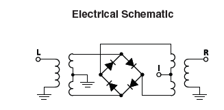
I am using an RF Mixer as a frequency down converter from 4.15GHz sine wave. I am trying to calculate the output Power from the IF port in dBm. 

The frequency and power going into the LO and RF ports are as follows:

LO = 4.15GHz, -2.5dBm

RF = 4.15GHz, -4.5dBm

Line impedance is 50ohm

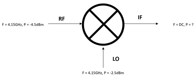
Since the RF and LO frequency are the approximately the same, I realise that the output frequency on IF will be near DC

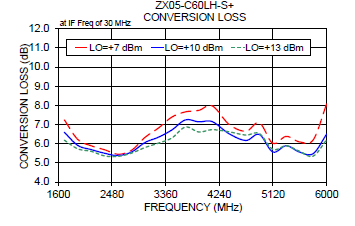
According to the datasheet of the mixer that I will be using (see link below), the conversion loss between RF and IF is 7.15 dB, does this figure get deducted from the RF input power?

 https://www.minicircuits.com/pdfs/ZX05-C60LH-S+.pdf

I do not understand what is happening from a power perspective in an RF mixer, can anyone suggest ways to calculate the Power output in dBm on IF?

Thank you

Parents
  • First thing is  to correctly visualize  is what is actually going on in the type of mixer you have chosen.  Stare at the schematic at the bottom of the page of the datasheet you linked to, and image the electron flow, until you can see how alternate half-cycles of LO serve to bias either one pair of diodes either on the left or the right, and then the other.

    Now,  if in your minds eye you replaced those diodes that are forward biased by a small resistor, and those diodes that are reverse biased with a small capacitor, you would be alternately grounding either the top or the bottom of the 'R transformer' secondary, and at the port I gets either a right way up or inverted version of the signal from R. Clearly at I the two ' L' terms cancel and the diode centre is a virtual earth - to within the matching of the diodes at least. This is in effect performing the multiplication of the RF signal by a bipolar square wave at the LO frequency, and then considering first the fundamental term of that square wave, and the angle product identity of your choice (cheers wikipedia) you see how a multiplication of two oscillating functions produces  the sum and difference terms emerging on the terminals.

    note that the LO level on your diagram is not going to work - your LO needs to be high enough to operate the diodes and you have selected a "level ten" mixer, so the transformers are designed to hitting the diodes with a volt or two p-p with 10dBm input  (10mW) coming in on the LO side. Once there is enough LO power to do this commutation, the conversion losses are almost independent of LO drive level. See how 6dBs  (4 to one power ratio) change of LO level move the conversion loss, less than the general wibbly-ness of the measurement.

    How much LO do you really have ?
    Now that '2' in the denominator says the RF to IF voltage ratio should half, and suggests a 6dB loss between RF level in, and IF level out, but that would only be for  diodes that do a perfect switch between on state of 1 - i.e. total conduction and 0 total block. Of course this is not true, real diodes are not like relay contacts wired as a reversing switch ! A dB or 2 of extra RF loss is to be expected. I'd probably put a 3dB pad on the board and design the rest of the line up as if it was 10dB conversion loss, and then I have the freedom to twiddle the resistors in the nominally 3dB pad after assembly to compensate for the inevitable uncertainties of real losses in cables, PCB tracks and so on.

    Don't forget to terminate the unwanted mixer frequencies too - just 'cos you don't need them does not mean they are not present on the mixer output, and the quoted performance assumes 50 ohm sources and loads on all 3 ports. Whatever you connect to the IF port must consider the sum frequency will be present  as well as the difference and at the least you should have an LPF /HPF split to divert everything that is too high to be useful to you, into a small resistor of 47 or 56 ohms - these being stadnard values that are usually near enough.

    Mike

    edited Tuesday to add pictures and some more words.

    PS

    If the derivation of the trig and angle stuff is not clear, perhaps  see

    examples on the bbc schools website

    https://www.bbc.co.uk/bitesize/guides/zsr334j/revision/1

    and a more formal derivation from trig.

    www.mathcentre.ac.uk/.../mc-ty-addnformulae-2009-1.pdf

  • Hi Mike

    Thank you so much for your reply, you have made me realise that there are a few gaps in my knowledge that I need to fill. I will go an do some research into your answer and I may get back to you with further questions

    I'm something of a beginner to RF and keen to learn more, I have a feeling I will be clocking up quite a few CPD hours on this 

    Thanks again! 

  • Please do come back when things make no sense - I found it hard to know what level you needed from your question, so threw in what I hope is enough-  but I'm happy to chew over any sticking points.

    The main thing about RF is that it is usually dominated by all the components not shown on the diagram - in the form of magnetic fields around currents (parasitic inductance, both mutual and self), charge pushed in one place due to some in another (stray capacitance) and the fact that all the things you thought of as simply connected are not at the same voltage as it takes time to get a signal to go from one place to another.
    Do realize that 4GHz is not an easy place to start - via holes in PCB are not negligible inductance, ;-) PCB is starting to look dispersive and electrically 'long' is anything more than a few cm in length and everything has a degree of transmission line like behaviour, and not the simple lossless model either. Move signals about in coax if you can.

    Mike.

Reply
  • Please do come back when things make no sense - I found it hard to know what level you needed from your question, so threw in what I hope is enough-  but I'm happy to chew over any sticking points.

    The main thing about RF is that it is usually dominated by all the components not shown on the diagram - in the form of magnetic fields around currents (parasitic inductance, both mutual and self), charge pushed in one place due to some in another (stray capacitance) and the fact that all the things you thought of as simply connected are not at the same voltage as it takes time to get a signal to go from one place to another.
    Do realize that 4GHz is not an easy place to start - via holes in PCB are not negligible inductance, ;-) PCB is starting to look dispersive and electrically 'long' is anything more than a few cm in length and everything has a degree of transmission line like behaviour, and not the simple lossless model either. Move signals about in coax if you can.

    Mike.

Children
No Data