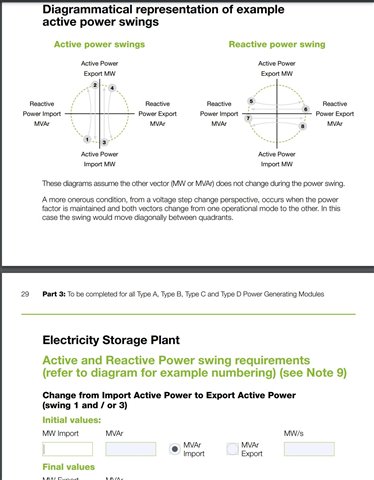
I am presently tasked to submit a G99 form to my DNO. I am struggling with part 3 in particular the section on active and reactive power swings. Can anyone enlighten me or recommend some reading.

I am presently tasked to submit a G99 form to my DNO. I am struggling with part 3 in particular the section on active and reactive power swings. Can anyone enlighten me or recommend some reading.
Are you the installer or end customer?
You need to know how the batteries will be used, how it will interact with any other generation or demand (existing or new) and how reactive power will be controlled / set.
For example, if you have a 5kVA battery inverter that can go from 100% max charge to 100% discharge over 10s, that's [5 - (-5) ] / 10 = 1kVA/s swing. Assuming running at a constant power factor separating into P and Q is easy. If you're running at a constant Q, you can work it out from the vectors (or let us know if you can't).
Note that it is the change in ESS output that is important. Even if you can't export, there will (may) still be a step change in the import.
Also from the DNO's point of view it is the ramp rate once the output starts changing that matters for P28 purposes. For frequency response systems, the latency of the controller is significant and the ramp rate of the actual inverter could be higher than simple inspection might suggest to compensate and still meet the service specification.
If it helps, the question arises because some battery plants are designed to provide frequency response services which will have the plant swing from full power export to full power import (or vice versa) in less than a second, so the MW/s could be several times the rated MW. This may cause flicker on the network unless steps are taken (e.g. a separate circuit to the substation). On the other hand, a domestic storage unit behind a G100 ELS controlled for peak shifting of a rooftop PV array may ramp slowly over several seconds; flicker is less likely to be a problem so the connection may be easier.
It is not unheard of for the ramp rate to be specified in the connection agreement, or it may be implicit in other connection documentation. Many inverters (assuming it is inverter-driven storage) have maximum ramp rate settings available where limits are required; factory default is usually as fast as possible.
Good afternoon Jam. I am the installer, I have just started with the company and it is all a bit new to me. I really appreciate your fantastic answer. What an excellent explanation. I am unable to work it out with vectors but would dearly like to know how to.
Once again thank you for your help.
Assuming you have equipment rated with an apparent power S (kVA) operating at a fixed PF (=cos(phi)) then
Active power (kW) = P = S x PF
Reactive power (kVAr) = Q = S x sin(phi) = S x sqrt( 1 - PF^2)
Then the active power swing is as above but all you need to consider are the "P parts" (i..e MW) of the initial and final. Likewise for the reactive power swing consider only the Q part (if you're running to generate significant reactive power, which is unlikely in many cases).
So if in my 5kVA example above you were operating at PF = 0.8, P1 = P2 = 4kW so 0.8kW/s over 1s.
If you have a fixed reactive power, then Q1 = Q2 and since Smax is fixed by the equipment, this places limits on P1 and P2 by rearranging the equations above. Reactive power swing is obviously zero, while active power swing is attained by just looking at the P parts again.
Thank you again. I have been playing around with this and think I am getting to grips with it.
We're about to take you to the IET registration website. Don't worry though, you'll be sent straight back to the community after completing the registration.
Continue to the IET registration site