Is measuring tower footing resistance still considered an effective strategy for preventing back-flashovers during lightning strikes in modern transmission systems?

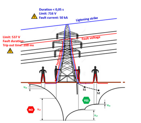
Lightning is one of the primary sources that cause failure on overhead transmission system. It is one of the most natural and serious cause of over voltage. These over voltages will result in flashover across an insulator and the resultant fault surge will tends to ‘damage’ and reduce the life span propagate along the line until it is extinguished, or the breaker operates. This movement of the surge currents of associated equipment such as circuit breakers and transformers and impacts network performance adversely.
Parents
  • I am based in the UK, so we don't get that many big thunderstorms.  Knowing the pylons are earthed is a considered quite important, as AJJ notes.


    A well- earthed tower == pylon is needed but on its own not enough - the design of the air horns and the presence or not of any surge protection at the ends is also a part of it.
    Just in case your technical definition is different, here we reserve the word transmission for the big stuff, hundreds of KV, that goes the length of the country on pylons, and they have the top wire earthing,


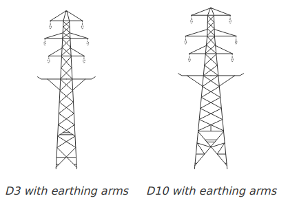
    A transmission tower / 'pylon'
    The earth wire is considered to have a 45 degree shade angle, so when the arms need to be wide, or the top has to be lower, then twin earth lines are fitted, to ensure 'cover' for both sides. This is often seen at the ends of a line as it comes into a transformer/ substation. Presumably this provides  a more reliable and lower impedance earth path.


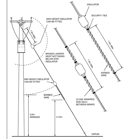
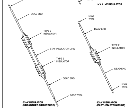
    In contrast,  33kV and 11kV are considered to be HV distribution, and these are shorter poles, usually insulating but with insulating gaps on the stay wires protecting the steel cross-bars. They generally supply a smaller area, and are not so tall, so are both less likely to be struck ,and less important if something trips when they are.


    image from ENW

    There  is a general agreement that about 10 ohms is an upper limit for network earths for pylons , but it is not clear where that comes from. For LV the corresponding unjustifiable figure is usually taken as 20 ohms....

    There are some useful additional references for the pylon stuff  in this rather wordy thesis

    https://orca.cardiff.ac.uk/id/eprint/42730/1/ahmeda%20-%20thesis%20final%20copy.pdf

    Mike

  • Hello Mike:

    It's a long time since i investigated high voltage ''transmission" involving pylons, so maybe you can enlighten me by answering a few questions:-

    1- I assume that the UK "transmission" only carries 3 phase AC- Any dc power imported into the county (say from France) has to be converted into AC --that is there is no dc power 'transmission" system in the UK.

    2- What 3 phase configuration is used - "STAR or DELTA"

    3- Are phase lines rotated in relation to earth periodically along the line?

    4- Are high voltage capacitors hard wired into the system periodically along the line?

    5- Where are grounding lines placed on the new T-Pylon "transmission" line?

    Peter Brooks

    Palm Bay Florida 

  • Its not my day job either I must say, but I have an interest ;-)

    So, 

    1) Yes the pylons carry 3 phase - usually as 2 independent circuits, thee phases on the left, and 3 on the right. These may split to different destinations at some point, and in any case it is quite common to switch one side off for maintenance, and leave the the other side on. Crews painting and checking for corrosion use coloured indicators to avoid climbing the wrong side. As the green and red flags seen at the start of this video. https://www.youtube.com/watch?v=EhIf6163H4c

    There are several versions oy pylon in use.  https://telcontar.net/Power/pylons/PL4

    I'd not like to say there is no DC overhead at all, as there may be in the vicinity of the inverter stations, but certainly all the stuff yomping over hills and vales is AC...

    2) all our HV, and for that matter even what in the US would be considered to be MV, down to 11 and 6kV  is carried as 3 phases without neutral, and the voltage referred to is the phase to phase delta  voltage. Only at the generation end, there are star or zig-zag transformers that earth the centre of the triangle, and earth fault relays are then used to disconnect the HV if there is any significant out of balance current, as this can only occur in a fault condition.


    3) there are transposition towers  https://telcontar.net/Power/pylons/comparisons-transposition#X  that rotate phases, to try and equalize the capacitance to ground from all 3 phases, though there are far fewer than there were when the National Grid was originally  constructed, as experience has shown over the years that the imbalance can be compensated more easily in other ways, and a lot of the anticipated problems with telephone systems and so on did not materialize.

    4) There are capacitors, and on the very high voltage network inductors as well, used to balance the line impedances. This is normally done on the same site as transformers as much as possible. There are  dynamic systems that can switch in more or less correction if required,

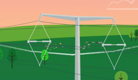
    5) good question. There are two,  one per triplet. The black wire above the 3 blue phases in the promotional graphic below from the National Grid presentation.
     earth wires on dual cct T pylons.

    When you know where to look, the photos show them in reality too but not doubled up like the phase cores.

    www.elandcables.com/.../t-pylons-make-their-uk-debut

    It is fair to say that there are not that many out in the wild yet and there may be other configurations.

    I'm also not sure how they will do in place of the "earthing" or "catcher" arms in the way they currently do where lines go over protected routes like railways, major roads and so on,

    The official name is earthing arms... Ensures any falling wire is dead before it hits the ground. So they tell me..

    Mike.

Reply
  • Its not my day job either I must say, but I have an interest ;-)

    So, 

    1) Yes the pylons carry 3 phase - usually as 2 independent circuits, thee phases on the left, and 3 on the right. These may split to different destinations at some point, and in any case it is quite common to switch one side off for maintenance, and leave the the other side on. Crews painting and checking for corrosion use coloured indicators to avoid climbing the wrong side. As the green and red flags seen at the start of this video. https://www.youtube.com/watch?v=EhIf6163H4c

    There are several versions oy pylon in use.  https://telcontar.net/Power/pylons/PL4

    I'd not like to say there is no DC overhead at all, as there may be in the vicinity of the inverter stations, but certainly all the stuff yomping over hills and vales is AC...

    2) all our HV, and for that matter even what in the US would be considered to be MV, down to 11 and 6kV  is carried as 3 phases without neutral, and the voltage referred to is the phase to phase delta  voltage. Only at the generation end, there are star or zig-zag transformers that earth the centre of the triangle, and earth fault relays are then used to disconnect the HV if there is any significant out of balance current, as this can only occur in a fault condition.


    3) there are transposition towers  https://telcontar.net/Power/pylons/comparisons-transposition#X  that rotate phases, to try and equalize the capacitance to ground from all 3 phases, though there are far fewer than there were when the National Grid was originally  constructed, as experience has shown over the years that the imbalance can be compensated more easily in other ways, and a lot of the anticipated problems with telephone systems and so on did not materialize.

    4) There are capacitors, and on the very high voltage network inductors as well, used to balance the line impedances. This is normally done on the same site as transformers as much as possible. There are  dynamic systems that can switch in more or less correction if required,

    5) good question. There are two,  one per triplet. The black wire above the 3 blue phases in the promotional graphic below from the National Grid presentation.
     earth wires on dual cct T pylons.

    When you know where to look, the photos show them in reality too but not doubled up like the phase cores.

    www.elandcables.com/.../t-pylons-make-their-uk-debut

    It is fair to say that there are not that many out in the wild yet and there may be other configurations.

    I'm also not sure how they will do in place of the "earthing" or "catcher" arms in the way they currently do where lines go over protected routes like railways, major roads and so on,

    The official name is earthing arms... Ensures any falling wire is dead before it hits the ground. So they tell me..

    Mike.

Children
No Data