
Quick question, is there anything a layman can check or repair if the alternator stops charging? Or is it a new one? Here's hoping!
Quick question, is there anything a layman can check or repair if the alternator stops charging? Or is it a new one? Here's hoping!
Some explanation so you know what you are looking at.
The electricity is generated in stator coils that 'stay' still and are wound into the frame. Usually 3 phases, and rectified with 6 diodes, On the ohm meter all 3 coils should look very low resistance, and the diodes will conduct 1 way, not the other. You can only sensibly test the diodes with the coils not connected to them, as all you read is another diode via the coils.
Spinning in the middle is an electro magnet, that is exited by a DC, through the reguator and this connects by 2 brushes. Again, the resistance should buzz out very low on the ohm meter.
The regulator alters the rotor current, winding it down at higher revs so that the product of velocity and magnetic field strength, and so generated voltage is more or less constant.
In a car type system, the 'ignition light' provides the initial excitatiokn to the rotor, until it generates enough to sustain itslef, for testing the reg can be removed, and the rotor just excited from 12V via a lamp - the lamp should glow and on spinning some volts should appear at the rectifier.
For any given model of alternator all this sort of thing, with numbers is usually available from the makers, but in order of easy fix and then liklihood, , igniion lamp fault, brushes fault, blown rectifier diode, dead reguator,
And look for mechanical things, like wet/corroded contact, or moving parts full of sand or even cobwebs.
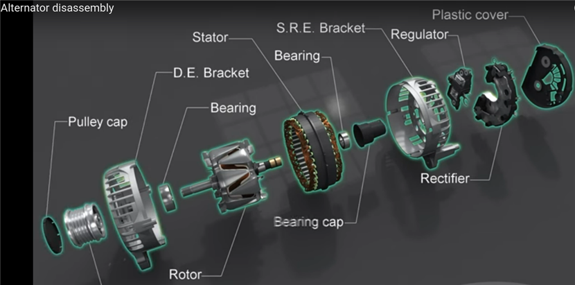
So the rotor in this example the bent pole pieces create alternating North and south poles in the stator windings, even though the rotor winding is a simple cylindrical solenoid wrapped around the shaft. The brushes are shown emerging from the regulator blok like 2 fangs ready to meet the slip rings.
Mike.
Some explanation so you know what you are looking at.
The electricity is generated in stator coils that 'stay' still and are wound into the frame. Usually 3 phases, and rectified with 6 diodes, On the ohm meter all 3 coils should look very low resistance, and the diodes will conduct 1 way, not the other. You can only sensibly test the diodes with the coils not connected to them, as all you read is another diode via the coils.
Spinning in the middle is an electro magnet, that is exited by a DC, through the reguator and this connects by 2 brushes. Again, the resistance should buzz out very low on the ohm meter.
The regulator alters the rotor current, winding it down at higher revs so that the product of velocity and magnetic field strength, and so generated voltage is more or less constant.
In a car type system, the 'ignition light' provides the initial excitatiokn to the rotor, until it generates enough to sustain itslef, for testing the reg can be removed, and the rotor just excited from 12V via a lamp - the lamp should glow and on spinning some volts should appear at the rectifier.
For any given model of alternator all this sort of thing, with numbers is usually available from the makers, but in order of easy fix and then liklihood, , igniion lamp fault, brushes fault, blown rectifier diode, dead reguator,
And look for mechanical things, like wet/corroded contact, or moving parts full of sand or even cobwebs.
So the rotor in this example the bent pole pieces create alternating North and south poles in the stator windings, even though the rotor winding is a simple cylindrical solenoid wrapped around the shaft. The brushes are shown emerging from the regulator blok like 2 fangs ready to meet the slip rings.
Mike.
We're about to take you to the IET registration website. Don't worry though, you'll be sent straight back to the community after completing the registration.
Continue to the IET registration site