Use of Type B MRCDR with no Neutral

We have Type B MRCDR's installed within our MDU/MDA assemblies. The manufacturer/model is Doepke - ELR-3BN+ residual current transformer.

They have been installed on supplies to VFD controlled equipment so we have followed manufacturers guidance.

My question is this.....The VFD equipment does not require a Neutral therefore only the 3 phases pass through the associated residual current transformer. 

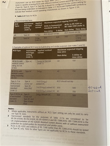
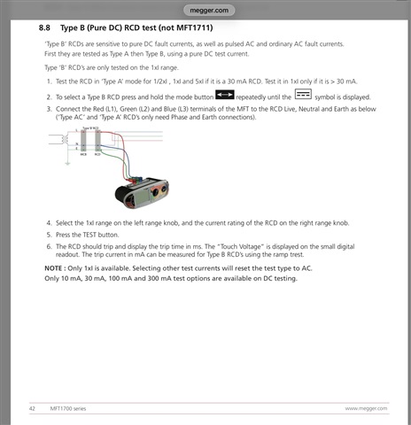
We were able to test the device as both a Type AC and a Type A and the device operates, it does not however operate as type B when this is selected on the MFT.

I may be worried about nothing as they are operational.

Please share your thoughts

  • I've not come across this type of kit before, so guessing really, but assuming the "CT" really is of the correct special type that will detect d.c. residual currents - my next guess was what setting did you have the MFT on? - from memory the d.c. trip levels for B-type RCDs differ from the nominal a.c. ones (from even vaguer memory) I think a 30mA B-type need not trip until 60mA d.c. for instance - I don't know if your MFT takes such things into consideration or just created a d.c. residual current of the specified setting (mine is old and doesn't have such features Frowning)

      - Andy.

  • If the Variable Frequency Drive is varying the frequency of the current will it sometimes produce Triplen Harmonics that will create high neutral currents that will not have anywhere to go?

  • high neutral currents that will not have anywhere to go?

    Only if things are connected in star - otherwise you just end up with differing line currents but no overall imbalance (like a single phase HV transformer connected L-L under 3-phase overheads with no N).

       - Andy.

  • I’m just trying to picture in my head what currents are following and where.

    Presumably the harmonic currents will circulate in the supply equipment possibly causing issues such as overheating?

  • Focusing upon the actual question asked.

    Here is a conundrum for you.

    The IET Guidance Note Three says the test current for a Type B RCD is 2x I delta n  smooth DC.

  • A Megger 1700’s series MFT will not do a 2x I delta n  smooth DC test.


    www.megger.com/.../MFT1711--MFT1721--MFT1731_UG_en.pdf

  • The hidden problem is that the fast switching edges (voltage & current) produce radiated and conducted emissions that affect other equipment.

    So.. The equipment hence has a load of filters (inductors and capacitors, shapes & sizes) to reduce these edges and frequencies, and most commonly that includes a link to Earth/CPC, even if no neutral is present. This provides the extra circuit loop for diverting the 'putative' neutral (aka 'unbalance') current, despite there being no physical neutral.

    It's that "most commonly that includes a link to Earth/CPC" part that catches most analyses. It's only a small proportion of the supply current but across a number of loads can be sufficient to trip RCDs or exceed allowable limits (e.g. combined 6 way extensions on the one plug)

    The choice of switching frequency in the inverters can also create that third harmonic that's nasty for neutral imbalance. Too many options!

  • Beware of the confusion between 'regular operating conditions' and 'forced test conditions'.

    The forced test conditions are typically designed to be easily created in a lab or production test set-up. They, via theory, are as onerous, or worse, than the trip level operating conditions, and are often about some hidden quality control (*). E,g, the magnetic characteristics of the internal ferro-coils.

    I have heard of a manufacturer (another product) who for many years used incremental amounts from some stock 'steel'. Product worked fine. Then they ran-out, and re-ordered some of the steel to the same steel standard, but the product started failing.

    They had not specified (and didn't know) which magnetic characteristics were important to them, and it's not part of the standards for steels. It feels like the type A/AC is like that. Same for the HP and B types. Lots of finger pointing and little clarity.

    The test conditions are 'forcing', rather than representative (of the poorly known) operating conditions for the many and various 'nasty' loads..

    (*) there's a similar test case for regular cables that assumed PVC (IIRC), which didn't match operating conditions (Naval Application/Standard) which meant that a perfectly good cable (better insulation) kept be failed by this test - it took a lot of persuasion to 'clarify' the test, separating Quality Control from Quality Assurance.

  • I had better be honest here, several years ago I attended the Elex Show at Coventry and I stood and had a conversation about RCD testing with Michael Peace, John Peckham and Graham Kenyon, so hopefully having talked about RCD testing with all three of them at the same time, hopefully I am getting it right.

    Michael wrote this IET Wiring Matters article about RCD testing.

    electrical.theiet.org/.../

  • The IET Guidance Note Three says the test current for a Type B RCD is 2x I delta n  smooth DC.

    A Megger 1700’s series MFT will not do a 2x I delta n  smooth DC test.

    So, for example, to test a 30mA B-type with DC (not that such a test is a requirement, but if we wanted to) .. we'd have to test with at least 60mA d.c. - which would mean setting the MFT at say 100mA x1 ?

       - Andy.