Assessing Voltage Dip Propagation for a Grid-Connected Industrial Facility

I'm working on a resilience study for a large industrial facility supplied from a grid substation shared with the local distribution network. The study follows process disruptions attributed to voltage dips originating on the supply side and propagating into the plant's internal network.

I'd like to invite the forum's experience on assessment approach.

The Problem:

Power quality monitoring at the point of common coupling has confirmed recurring voltage dips, propagating through step-down transformers into the plant network and causing undervoltage-related trips on large motors and variable-speed drives, along with associated production disruption. The plant has no local generation and is fully dependent on the grid connection.

Assessment Approach:

I'm modelling the network from the point of common coupling down to the plant's internal distribution level, to characterise dip propagation and assess vulnerability at each load point. This includes calibrating fault conditions to replicate recorded dip behaviour, representing dynamic motor loads for drives known to trip during these events, and running sensitivity cases across the recorded event envelope.

A key outstanding item is the grid fault strength and impedance angle at the point of common coupling, currently being pursued through the utility.

What I'm Seeking:

  • What modelling approach has given the most reliable correlation with measured plant behaviour, particularly for motor dynamics and drive representation?
  • How have others handled the grid equivalent at the point of common coupling when utility fault-level data is unavailable or uncertain?
  • Is there value in assessing harmonic performance alongside dip propagation for a plant of this nature, or is that generally treated as a separate exercise?
  • Where the utility grid is the source and the plant has no control over it, what contractual or regulatory mechanisms have others used to engage the utility on power quality obligations?

Broader Question:

This looks like a systemic issue for facilities drawing from shared substations serving mixed industrial and distribution loads. Is there published guidance specifically addressing voltage dip assessment methodology for large grid-connected industrial plants, beyond standard equipment immunity testing references?

Grateful for any experience or critique of the approach above.

  • EN 50160 might be worth a look - it may not be intended to apply directly to the 220kV side of things but something similar should and the numbers ought to scale.
    (BS EN 50160:2022 outlines the voltage characteristics of electricity supplied by public networks).
    To ride through a drop out, you need to store rather more energy than would 'fill in the gaps' either as L_C storage or as a spinning flywheel., and the numbers you mention are very high for that sort of trick. 
    I;d be looking at delays on the low voltage trips if that is at all possible, and maybe changing some alumnium for steel in the rotating parts to give more inertial storage if that is appropriate. 

    In terms of mitigating the shocks from the arcs themselves, this is a fun read of some Spanish research. In summary, arc furnaces are not good partners to share a supply with but things can be done to help a bit.  

    Mike.

  • Mike - thanks, both very useful.

    On EN 50160: agreed it won't transfer numerically to 220 kV, but the classification framework (residual voltage × duration bands) is exactly what I needed as a template - I'll bucket our 32 recorded events the same way and use that structure when I take this to BBMB. The standard doesn't assign expected dip frequency or operator responsibility, so it won't hand me a contractual limit outright, but it gives me a clean, recognized way to present the data rather than a raw list of numbers.

    On storage sizing - good catch, and worth clarifying where I'm actually headed: I'm leaning STATCOM at the 220 kV PCC rather than DVR/BESS, so it's a shunt reactive-current injection rather than a real-power/energy device. That sidesteps the "need to store more than fills the gap" issue directly, since it's not storing energy to bridge the event at all.

    But your point still bites in a different form. STATCOM voltage recovery is capped by injected current relative to how weak the grid has gone during the event, not by energy - and our recorded envelope goes down to 10% residual voltage in places, which is a genuinely deep event. A shunt device sized off the average dip could under-perform on the worst 10-20% residual cases specifically. So I'm going to run our full recorded event set through the ETAP model and check STATCOM MVAr sizing against the deepest events individually, not just a typical case, before I commit to a rating.

    On the arc furnace paper - useful confirmation. The results back up what I'd assumed: SVC there did essentially nothing for voltage/current THD (current THD actually roughly doubled with the SVC in, from the TCR's own harmonics) but cut long-term flicker substantially. That lines up with keeping SVC in our study as a furnace-side flicker/PF tool only, separate from the PCC dip-mitigation question.

    Will also look at UV trip delay and the inertia point for the rolling mill drives - cheap to explore relative to any power-electronics option.

    Thanks again - this is exactly the kind of sanity-check I was hoping for.

    Abhishek

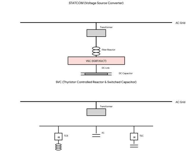
  • My understanding of the 'STATCOM' (Static Synchronous Compensator) unlike an SVC (Static Var Compensator )approach is the electronics looks like most of the invertetr guts of a UPS without the battery bits, but with some large capacitors storing the DC voltage (labelled DC-link in the drawing below, shamelessly nicked from google.)

    These DC capacitors still need to be sized to store rather more than the maximum energy you wish to in-fill if the drop out is multi-cycle and affects all phases. During a drop out that affects only one phase-phase voltage,  or that lasts only for one part of a cycle, there is some chance to refill that reservoir from the other  bits of supply waveform that are not missing, so it can be rather smaller. 


    Mike.

  • Yes it makes sense, thanks. So my ETAP transient stability run gives me the MVAr rating and response time needed at the PCC from the recorded dip events, but the DC-link capacitor design itself sits with the vendor. I'll pass on our worst-case symmetric, multi-cycle dip data specifically in the RFQ so they're not sizing the DC-link off an average case.

    Abhishek