I am currently undertaking a HV system resilience study for a large heavy industrial facility (steel manufacturing including arc furnace, electric smelting, cold rolling, and hot rolling mill drives) drawing power at 220 kV from a grid substation that is shared with the city distribution network. The study has been commissioned following repeated and well-documented process disruptions caused by voltage dips originating from the 220 kV grid, propagating through the plant's step-down transformers (100 MVA, 220/11 kV) into the 11 kV plant network.
I would like to share the problem in detail and invite the forum's experience on both the simulation methodology and practical mitigation strategies, particularly from those who have worked on similar heavy industrial or grid-connected plant studies.
The Problem:
The 220 kV supply is taken from a grid substation shared between the industrial facility and the city distribution network. SCADA and power quality monitoring data has confirmed recurring voltage dips at the 220 kV Point of Common Coupling (PCC) with the following characteristics:
- Dip magnitudes ranging from 10% to 60% of nominal voltage
- Durations ranging from 10 ms to 400 ms
- Both symmetrical and asymmetrical events recorded
- Events correlating with switching operations, fault clearance, and load changes elsewhere on the shared grid
These dips propagate through four 100 MVA, 220/11 kV step-down transformers into the 11 kV plant busbars, where they cause:
- Undervoltage trips on large induction motors (arc furnace, electric smelting reactor, cold rolling drives, hot rolling mill)
- VFD undervoltage faults causing process-critical drives to trip
- Motor contactor drop-out on auxiliary plant
- Production interruptions with significant financial and process safety consequences
- Over 32 documented dip events in a single financial year (FY2025-26) captured across multiple plant areas
The plant has no local generation and is entirely dependent on this 220 kV grid connection.
Study Approach:
I am building an ETAP Transient Stability model of the system, scoped from the 220 kV PCC down to the 11 kV plant busbars, to characterise the propagation of dips and assess the vulnerability of each load bus. The modelling approach includes:
- Calibrating fault impedance at the PCC bus to replicate SCADA-recorded dip magnitudes
- Dynamic motor models for drives confirmed tripping in SCADA/PLC logs (inertia, load torque characteristic, locked rotor current)
- Lumped static loads for non-critical buses
- Simulation time extended beyond 1 second to capture post-dip motor recovery behaviour
- Sensitivity runs across the recorded dip magnitude and duration envelope (10% to 60%, 10 ms to 400 ms)
The key outstanding data item is the grid fault MVA and X/R ratio at the 220 kV PCC, which I am pursuing through the utility. Everything else including motor nameplates, VFD setpoints, connected load lists, and timestamped trip logs has been compiled from plant records.
What I Am Seeking From the Forum:
On Simulation Methodology:
- For those who have modelled voltage dip propagation in ETAP or PSS/E for similar heavy industrial plants, what modelling approach gave you the most reliable correlation with measured plant behaviour? Specifically around motor dynamic models and VFD representation.
- How have you handled the grid equivalent at the PCC when utility fault level data is unavailable or uncertain? Have you used sensitivity studies, worst/best case bounds, or something else?
- Is there value in running a frequency scan or harmonic analysis alongside the transient stability study for an arc furnace plant of this nature, or is that a separate workstream entirely?
On Mitigation Strategies:
- For plants of this scale (100 MVA transformers, arc furnace and rolling mill loads on 11 kV), what mitigation measures have proven most effective in practice? I am currently evaluating the following options:
- Dynamic Voltage Restorer (DVR) on the 11 kV bus
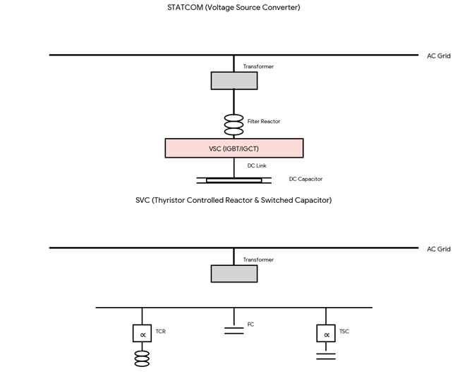
- STATCOM or SVC at the 220 kV PCC
- BESS for critical load ride-through
- VFD ride-through parameter optimisation (kinetic buffering, undervoltage trip delay)
- Motor protection relay setting review, specifically extending undervoltage trip time delay to ride through transient dips
- Busbar sectionalisation to separate sensitive process loads from dip-exposed buses
- On-load tap changer response optimisation on the 220/11 kV transformers
- Has anyone implemented a DVR or STATCOM on a comparable heavy industrial plant? What were the practical challenges around sizing, response time, and integration with existing protection?
- For VFD ride-through optimisation, what is the realistic ride-through capability of modern VFDs during dips of 40% to 60% magnitude, and is kinetic buffering a viable strategy for high-inertia rolling mill drives?
- Where the utility grid is the source of dips and the plant has no control over the 220 kV network, what contractual or regulatory mechanisms have others used to engage the utility on Power Quality obligations, and has this led to any grid-side improvements?
Broader Question:
This appears to be a systemic issue in facilities that draw power from shared utility substations serving mixed industrial and distribution loads. The plant has no means to control or predict the grid-side events yet bears the full operational and financial consequence.
Is there published IET, CIGRE, or IEEE guidance specifically addressing voltage dip mitigation strategy selection for large HV-connected industrial plants? I am aware of IEC 61000-4-11 and IEC 61000-4-34 for equipment immunity testing but am looking for something more at the system study and mitigation design level.
I would be grateful for any experience, references, or critique of the approach described above.
Abhishek Prasad, MIET
Electrical Engineer, Power Systems