This discussion is locked.
You cannot post a reply to this discussion. If you have a question start a new discussion

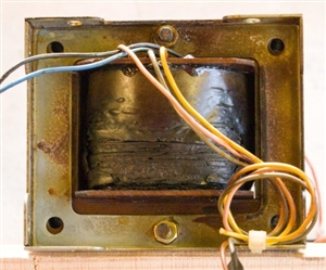
DC injection braking and a burned out transformer

I have been fettling a lathe which was fitted with DC injection braking. I was a bit unsure about the condition of the components in an enclosure on the back, but having looked up a bit about motor control circuits and having learned about ladder diagrams, I have satisfied myself that I know what has happened.


At some stage, a transformer (240/130V) has burned out. That leaves two questions: (1) why? and (2) what is the spec of the old one?


The horizontal surfaces of the enclosure and its contents have been covered by a thin brown layer, which I assume is vapourised enamel from the transformer windings, but there is no evidence of any further damage.


Father taught me never to replace a fuse without finding the fault which blew it. Along the same lines, I want to be satisfied that none of the other components has caused a short circuit. However, it appears that it is the primary which has overheated. So my first question is what would happen if the secondary of a transformer is shorted. Would it be fried? Woud the primary be fried? Or would both be fried?


My second difficulty is determining the spec of the transformer. The circuit diagram has "N" and "240" on the primary side, and "Z" and "130" on the secondary side. I assume that this means that the secondary provides 130 V, which after rectification, is fed to the motor. The problem is that there are no markings on the transformer. The manufacturer of the unit ceased trading 10+ years ago, so no help there. The motor plate specifies 6.4/3.7 A. The transformer wires (both sides) are about 4.2 sqmm CSA so good for 3 - 5 A (?). Based on a weight of 4.0 kg and the transformer's dimensions, and comparing them with current models; I am guessing that a 320 VA transformer is required. My second question is whether my above reasoning is sound.


Before anybody else says it, yes, I think that I could get a modern module which will do the job, but isn't it more satisfying to fix rather than replace?
eabde54935c495ab8feb4fb009758b5e-huge-20190425transformer.jpg

Parents
  • Ah I love the smell of hot varnish first thing in the morning...

    Based on many teenage attempts to rewind transformers that looked a bit like that, I'd suggest this has most likely suffered from shorted turn syndrome - where the insulation has failed between adjacent layers of  winding. Once a shorted turn has formed, the primary current is very high even under no load, and total failure soon follows. 

    If the failure is in the outer layers  it is more often due to mechanical damage, if internal failed, and more cooked inside than out, then usually slow cooking due to poor cooling/sustained overload.

    The wattage you can estimate from the iron area of the central leg as this will give you a volts per turn, and then if you can estimate the wattage from no of turns and  wire size.  Equally, assuming the C to T ratio of the laminations is pretty much optimum, then a Tx of the same weight is a good measure.

    The modern trend is to include a thermal trip in the winding bundle, which makes this sort of thing much less dangerous  than it once was. If you are short of space a toroid and a fan might allow more watts per cubic inch, which translates to an ice-cold solution, which in turn means reliability.


    What is the 2ndry load - can you sketch out the rectifiers and so on - it may never have been man enough, or there may be a failed diode in the rectifier causing an overload.

    IF you can get a rectifier part no. we can get a supporting figure for the design load. If  it has been off for a few years, be aware that electrolytic caps tend to fail with a bang if brought back on the full volts suddenly - I sometimes  run old electronics if the 1960s an earlier with a lamp in series to give a trickle charge for a few mins before first power on. Also if there is a fault, then the lamp comes on, which  is a safe failure mode.
Reply
  • Ah I love the smell of hot varnish first thing in the morning...

    Based on many teenage attempts to rewind transformers that looked a bit like that, I'd suggest this has most likely suffered from shorted turn syndrome - where the insulation has failed between adjacent layers of  winding. Once a shorted turn has formed, the primary current is very high even under no load, and total failure soon follows. 

    If the failure is in the outer layers  it is more often due to mechanical damage, if internal failed, and more cooked inside than out, then usually slow cooking due to poor cooling/sustained overload.

    The wattage you can estimate from the iron area of the central leg as this will give you a volts per turn, and then if you can estimate the wattage from no of turns and  wire size.  Equally, assuming the C to T ratio of the laminations is pretty much optimum, then a Tx of the same weight is a good measure.

    The modern trend is to include a thermal trip in the winding bundle, which makes this sort of thing much less dangerous  than it once was. If you are short of space a toroid and a fan might allow more watts per cubic inch, which translates to an ice-cold solution, which in turn means reliability.


    What is the 2ndry load - can you sketch out the rectifiers and so on - it may never have been man enough, or there may be a failed diode in the rectifier causing an overload.

    IF you can get a rectifier part no. we can get a supporting figure for the design load. If  it has been off for a few years, be aware that electrolytic caps tend to fail with a bang if brought back on the full volts suddenly - I sometimes  run old electronics if the 1960s an earlier with a lamp in series to give a trickle charge for a few mins before first power on. Also if there is a fault, then the lamp comes on, which  is a safe failure mode.
Children
No Data