This discussion is locked.
You cannot post a reply to this discussion. If you have a question start a new discussion

DC injection braking and a burned out transformer

I have been fettling a lathe which was fitted with DC injection braking. I was a bit unsure about the condition of the components in an enclosure on the back, but having looked up a bit about motor control circuits and having learned about ladder diagrams, I have satisfied myself that I know what has happened.


At some stage, a transformer (240/130V) has burned out. That leaves two questions: (1) why? and (2) what is the spec of the old one?


The horizontal surfaces of the enclosure and its contents have been covered by a thin brown layer, which I assume is vapourised enamel from the transformer windings, but there is no evidence of any further damage.


Father taught me never to replace a fuse without finding the fault which blew it. Along the same lines, I want to be satisfied that none of the other components has caused a short circuit. However, it appears that it is the primary which has overheated. So my first question is what would happen if the secondary of a transformer is shorted. Would it be fried? Woud the primary be fried? Or would both be fried?


My second difficulty is determining the spec of the transformer. The circuit diagram has "N" and "240" on the primary side, and "Z" and "130" on the secondary side. I assume that this means that the secondary provides 130 V, which after rectification, is fed to the motor. The problem is that there are no markings on the transformer. The manufacturer of the unit ceased trading 10+ years ago, so no help there. The motor plate specifies 6.4/3.7 A. The transformer wires (both sides) are about 4.2 sqmm CSA so good for 3 - 5 A (?). Based on a weight of 4.0 kg and the transformer's dimensions, and comparing them with current models; I am guessing that a 320 VA transformer is required. My second question is whether my above reasoning is sound.


Before anybody else says it, yes, I think that I could get a modern module which will do the job, but isn't it more satisfying to fix rather than replace?
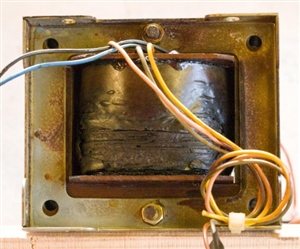
eabde54935c495ab8feb4fb009758b5e-huge-20190425transformer.jpg

Parents
  • Well spotted- the AC inputs should each see one kathode and one anode, and the positive output should be 2 kathodes, and the negative output should be 2 anodes.


    The  data sheet for the rectifier indicates it is a 25 amp part, rated at  a mere 200v for reverse breakdown.  A rectifier rating of 25A forward feels like overkill, given what you said about the wire sizes, though that rating assumes you have it on a 25 degree C cold plate. However the 200V reverse, (noting a 110V RMS is more like 145v pk) seems to leave very little margin for the sort of 'flash and pop' surges often seen when contacts close on motor shuddering to a halt.  (the data sheet notes that 140V RMS is the limit for the 200V part.) However, if it passes the 'am I a diode' tests with the meter, then you are OK to keep it in there. (there are plenty of similar parts made of varying ratings  examples of bridges from the CPC catalogue. )


    The current rating of wire when wound into a transformer is a funny function of the wire packing density, and its ability to cool via conduction through the rest of the winding, and the fact that the skin depth is far more serious than normal, because the magnetic field vs current is higher than the free space case. However the key thing is that the BS7671 wire rating values are miles off.

    Luckily others have done the work for us , and there is a good reference for wire size versus cu rent in winding for low power 50Hz mains transformers here,  though in summary about 3-4 A per mm2 seems about right and if your wire sizes are  CSA in  mm2, then suggests only an amp or 2 for the windings you have. (I did say the BS7671 values were miles out for transformers didn't I..) This is more like 250VA, so not fitting that well with the 4 kilo weight. It may never have been fully optimised, if it predated CAD, that is quite likely.

    Indeed if you are very brave, his "how to roll your own" article from the same website is very informative too see here.  Nowadays I only would only ever countenance this if I had a need to replace some special part for for some very odd voltage, as life is too short, and there are plenty of transformers in the catalogues, but I remember winding replacement transformer of a couple of hundred watts  with about ten secondaries to restore an oscilloscope many years ago, and it taking forever (probably about 2 weeks of evenings) just to wind the thing. I have used a lathe on freewheel as a manual winding machine, but even so it quickly gets painful, and hand winding never seems to manage to get quite as many turns in as the original manufactured item.


Reply
  • Well spotted- the AC inputs should each see one kathode and one anode, and the positive output should be 2 kathodes, and the negative output should be 2 anodes.


    The  data sheet for the rectifier indicates it is a 25 amp part, rated at  a mere 200v for reverse breakdown.  A rectifier rating of 25A forward feels like overkill, given what you said about the wire sizes, though that rating assumes you have it on a 25 degree C cold plate. However the 200V reverse, (noting a 110V RMS is more like 145v pk) seems to leave very little margin for the sort of 'flash and pop' surges often seen when contacts close on motor shuddering to a halt.  (the data sheet notes that 140V RMS is the limit for the 200V part.) However, if it passes the 'am I a diode' tests with the meter, then you are OK to keep it in there. (there are plenty of similar parts made of varying ratings  examples of bridges from the CPC catalogue. )


    The current rating of wire when wound into a transformer is a funny function of the wire packing density, and its ability to cool via conduction through the rest of the winding, and the fact that the skin depth is far more serious than normal, because the magnetic field vs current is higher than the free space case. However the key thing is that the BS7671 wire rating values are miles off.

    Luckily others have done the work for us , and there is a good reference for wire size versus cu rent in winding for low power 50Hz mains transformers here,  though in summary about 3-4 A per mm2 seems about right and if your wire sizes are  CSA in  mm2, then suggests only an amp or 2 for the windings you have. (I did say the BS7671 values were miles out for transformers didn't I..) This is more like 250VA, so not fitting that well with the 4 kilo weight. It may never have been fully optimised, if it predated CAD, that is quite likely.

    Indeed if you are very brave, his "how to roll your own" article from the same website is very informative too see here.  Nowadays I only would only ever countenance this if I had a need to replace some special part for for some very odd voltage, as life is too short, and there are plenty of transformers in the catalogues, but I remember winding replacement transformer of a couple of hundred watts  with about ten secondaries to restore an oscilloscope many years ago, and it taking forever (probably about 2 weeks of evenings) just to wind the thing. I have used a lathe on freewheel as a manual winding machine, but even so it quickly gets painful, and hand winding never seems to manage to get quite as many turns in as the original manufactured item.


Children
No Data