This discussion is locked.
You cannot post a reply to this discussion. If you have a question start a new discussion

DC injection braking and a burned out transformer

I have been fettling a lathe which was fitted with DC injection braking. I was a bit unsure about the condition of the components in an enclosure on the back, but having looked up a bit about motor control circuits and having learned about ladder diagrams, I have satisfied myself that I know what has happened.


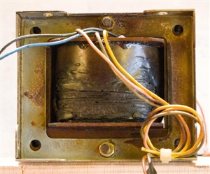
At some stage, a transformer (240/130V) has burned out. That leaves two questions: (1) why? and (2) what is the spec of the old one?


The horizontal surfaces of the enclosure and its contents have been covered by a thin brown layer, which I assume is vapourised enamel from the transformer windings, but there is no evidence of any further damage.


Father taught me never to replace a fuse without finding the fault which blew it. Along the same lines, I want to be satisfied that none of the other components has caused a short circuit. However, it appears that it is the primary which has overheated. So my first question is what would happen if the secondary of a transformer is shorted. Would it be fried? Woud the primary be fried? Or would both be fried?


My second difficulty is determining the spec of the transformer. The circuit diagram has "N" and "240" on the primary side, and "Z" and "130" on the secondary side. I assume that this means that the secondary provides 130 V, which after rectification, is fed to the motor. The problem is that there are no markings on the transformer. The manufacturer of the unit ceased trading 10+ years ago, so no help there. The motor plate specifies 6.4/3.7 A. The transformer wires (both sides) are about 4.2 sqmm CSA so good for 3 - 5 A (?). Based on a weight of 4.0 kg and the transformer's dimensions, and comparing them with current models; I am guessing that a 320 VA transformer is required. My second question is whether my above reasoning is sound.


Before anybody else says it, yes, I think that I could get a modern module which will do the job, but isn't it more satisfying to fix rather than replace?
eabde54935c495ab8feb4fb009758b5e-huge-20190425transformer.jpg

Parents
  • Glad you have restored it to operation, though it sounds like a bit of a beast, perhaps, given they could not draw a bridge rectifier correctly, the maker's datasheet was muddied with figures for a larger model. Thinking in terms of not cooking things, what stops the DC flowing  when it is all stationary and  no longer needed ?

    The stopping force is proportional to the B field, in turn proportional to the DC current so yes  some peak current limit in the form of a resistance on the DC side would do. I'd be less sure of using any resistance in series with the transformer primary, as while the brake is not applied the transformer load is almost nil, so the voltage reduction is not very much at the instant the brakes come on, and yet may be too much once the braking current has started to flow. Equally having a sharp initial brake, and then a more gentle slow-down may be quite acceptable.


    Or, as a quick try out, if you have 110v in the shop, how well does it work with that on the primary instead of 240? That would show you the effect of halving the voltage, and the voltage division would not be so load dependant. I might try a lamp dimmer, but not all designs of dimmer are happy on an inductive load. The simplest is resistance on the load side, and wire wound resistors of the metal clad kind are very forgiving of gross overloads (being little more than a heating element cast in ceramic in a metal tube ) Resistors that are a light evaporation of metal or other conductor on a ceramic rod (metal film / carbon film) tend to be self-fusing in overload, so I'd avoid those.


    Estimating the resistor values may be a bit odd, as you may think that one looks at the voltage and the windings resistance and there are the amps, but the  winding is a bit of a complex thing, and really the current will build slowly though the inductance.  You may think you need 10A, and at 110V, a total of 11 ohms will do, but that is not the full story,  so some experiment may be needed. You  may want to design a dropper with a no of higher value resistors in parallel, both to allow  some adjustment, and to provide  some be robustness against any single failure.

Reply
  • Glad you have restored it to operation, though it sounds like a bit of a beast, perhaps, given they could not draw a bridge rectifier correctly, the maker's datasheet was muddied with figures for a larger model. Thinking in terms of not cooking things, what stops the DC flowing  when it is all stationary and  no longer needed ?

    The stopping force is proportional to the B field, in turn proportional to the DC current so yes  some peak current limit in the form of a resistance on the DC side would do. I'd be less sure of using any resistance in series with the transformer primary, as while the brake is not applied the transformer load is almost nil, so the voltage reduction is not very much at the instant the brakes come on, and yet may be too much once the braking current has started to flow. Equally having a sharp initial brake, and then a more gentle slow-down may be quite acceptable.


    Or, as a quick try out, if you have 110v in the shop, how well does it work with that on the primary instead of 240? That would show you the effect of halving the voltage, and the voltage division would not be so load dependant. I might try a lamp dimmer, but not all designs of dimmer are happy on an inductive load. The simplest is resistance on the load side, and wire wound resistors of the metal clad kind are very forgiving of gross overloads (being little more than a heating element cast in ceramic in a metal tube ) Resistors that are a light evaporation of metal or other conductor on a ceramic rod (metal film / carbon film) tend to be self-fusing in overload, so I'd avoid those.


    Estimating the resistor values may be a bit odd, as you may think that one looks at the voltage and the windings resistance and there are the amps, but the  winding is a bit of a complex thing, and really the current will build slowly though the inductance.  You may think you need 10A, and at 110V, a total of 11 ohms will do, but that is not the full story,  so some experiment may be needed. You  may want to design a dropper with a no of higher value resistors in parallel, both to allow  some adjustment, and to provide  some be robustness against any single failure.

Children
No Data