This discussion is locked.
You cannot post a reply to this discussion. If you have a question start a new discussion

DC injection braking and a burned out transformer

I have been fettling a lathe which was fitted with DC injection braking. I was a bit unsure about the condition of the components in an enclosure on the back, but having looked up a bit about motor control circuits and having learned about ladder diagrams, I have satisfied myself that I know what has happened.


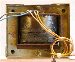
At some stage, a transformer (240/130V) has burned out. That leaves two questions: (1) why? and (2) what is the spec of the old one?


The horizontal surfaces of the enclosure and its contents have been covered by a thin brown layer, which I assume is vapourised enamel from the transformer windings, but there is no evidence of any further damage.


Father taught me never to replace a fuse without finding the fault which blew it. Along the same lines, I want to be satisfied that none of the other components has caused a short circuit. However, it appears that it is the primary which has overheated. So my first question is what would happen if the secondary of a transformer is shorted. Would it be fried? Woud the primary be fried? Or would both be fried?


My second difficulty is determining the spec of the transformer. The circuit diagram has "N" and "240" on the primary side, and "Z" and "130" on the secondary side. I assume that this means that the secondary provides 130 V, which after rectification, is fed to the motor. The problem is that there are no markings on the transformer. The manufacturer of the unit ceased trading 10+ years ago, so no help there. The motor plate specifies 6.4/3.7 A. The transformer wires (both sides) are about 4.2 sqmm CSA so good for 3 - 5 A (?). Based on a weight of 4.0 kg and the transformer's dimensions, and comparing them with current models; I am guessing that a 320 VA transformer is required. My second question is whether my above reasoning is sound.


Before anybody else says it, yes, I think that I could get a modern module which will do the job, but isn't it more satisfying to fix rather than replace?
eabde54935c495ab8feb4fb009758b5e-huge-20190425transformer.jpg

Parents
  • Mike and Kelly, thank you for your help.


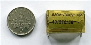
    I have tested the three big capacitors, which are indeed in parallel, and they are within spec. They are 470 μF and 385 V. However, the capacitor below is clearly not happy so whilst the board was out, I thought that I should replace it. It gives a reading of 0.5 μF against a spec of 0.1 μF. Whether it is the cause of the problem remains to be established. I cannot see any other obvious faults.


    I had thought of plugging in the motor direct. It would be a bit of a faff. Is it safe to plug it in and switch on?

    be5ea5c38056a46421b6fd8e43e511c1-huge-209dc6a9-21f2-4ec1-83b3-6056e2d6a76a.jpg

Reply
  • Mike and Kelly, thank you for your help.


    I have tested the three big capacitors, which are indeed in parallel, and they are within spec. They are 470 μF and 385 V. However, the capacitor below is clearly not happy so whilst the board was out, I thought that I should replace it. It gives a reading of 0.5 μF against a spec of 0.1 μF. Whether it is the cause of the problem remains to be established. I cannot see any other obvious faults.


    I had thought of plugging in the motor direct. It would be a bit of a faff. Is it safe to plug it in and switch on?

    be5ea5c38056a46421b6fd8e43e511c1-huge-209dc6a9-21f2-4ec1-83b3-6056e2d6a76a.jpg

Children
No Data