This discussion is locked.
You cannot post a reply to this discussion. If you have a question start a new discussion

DC injection braking and a burned out transformer

I have been fettling a lathe which was fitted with DC injection braking. I was a bit unsure about the condition of the components in an enclosure on the back, but having looked up a bit about motor control circuits and having learned about ladder diagrams, I have satisfied myself that I know what has happened.


At some stage, a transformer (240/130V) has burned out. That leaves two questions: (1) why? and (2) what is the spec of the old one?


The horizontal surfaces of the enclosure and its contents have been covered by a thin brown layer, which I assume is vapourised enamel from the transformer windings, but there is no evidence of any further damage.


Father taught me never to replace a fuse without finding the fault which blew it. Along the same lines, I want to be satisfied that none of the other components has caused a short circuit. However, it appears that it is the primary which has overheated. So my first question is what would happen if the secondary of a transformer is shorted. Would it be fried? Woud the primary be fried? Or would both be fried?


My second difficulty is determining the spec of the transformer. The circuit diagram has "N" and "240" on the primary side, and "Z" and "130" on the secondary side. I assume that this means that the secondary provides 130 V, which after rectification, is fed to the motor. The problem is that there are no markings on the transformer. The manufacturer of the unit ceased trading 10+ years ago, so no help there. The motor plate specifies 6.4/3.7 A. The transformer wires (both sides) are about 4.2 sqmm CSA so good for 3 - 5 A (?). Based on a weight of 4.0 kg and the transformer's dimensions, and comparing them with current models; I am guessing that a 320 VA transformer is required. My second question is whether my above reasoning is sound.


Before anybody else says it, yes, I think that I could get a modern module which will do the job, but isn't it more satisfying to fix rather than replace?
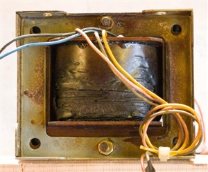
eabde54935c495ab8feb4fb009758b5e-huge-20190425transformer.jpg

  • I'd be wary of that cap - what was it wired between ? Usually means it has flashed internally, producing hot gas, and cracking the case.

    it was one of these metalised paper devices, falling from favour nowadays    PME261EC6100KR30 is the original maker's part no.


     modern near equivalent  would be metalised polypropylene, this one is rated to 305VAC,  higher voltage types are available but not so common. Temp ratings not so hot.  

    there are better modern metalised paper - price and large size reflects the lack of demand.


  • mapj1:

    I'd be wary of that cap - what was it wired between ? Usually means it has flashed internally, producing hot gas, and cracking the case.


    One end appears to go to nothing other than the earth connexion, which I don't quite understand.


    I am beginning to think that it would be easier to update the electronics, but I much prefer repair to replacement whenever possible.
  • If it is connecting to the earth then it is likely to be a Y suppression capacitor.  VFDs are very noisy for EMC and will generally have a pair of Y caps and an X2 cap as a delta on the supply usually along with a common mode choke.  Not surprised it has failed in the last 30 years.  Given one good voltage surge on the mains and considering plenty of locations get hundreds of >1000v surges per year it's no surprise it's given up.  There is a slim chance failed suppression could be allowing noise to upset the VFD control circuit at certain frequencies.  


    My starting point for old pcbs it to reflow (or hand touch) the soldering to eliminate cracked and dry joints, replace the electrolytics or test every capacitor. 75% of the time it then works fine.


    Unless you have three phase available you won't be able to plug the motor in DOL.  Even then you'll need to swap it to 400v (star) from 230v (delta).  


  • Sailbadthesinner:

    Unless you have three phase available you won't be able to plug the motor in DOL.  Even then you'll need to swap it to 400v (star) from 230v (delta).  


    I just knew it wasn't going to be as simple as wiring up a plug and switching it on! I do have three phase, but I'd have to remove the motor and bolt it down 'cos that would be easier than shifting the whole lathe. Sometimes I wonder how we got it in place originally! ?


    I ordered a replacement capacitor (actually, minimum order 5) from RS at 17:50 last night, and they arrived at about 09:00 this morning. How do they do that? ?


    Any road, today I have been rewiring a Victorian cottage, so I have no energy left for the electronics. ?

  • Update


    I think that I have fixed it. ?


    I took the motor to a local specialist who kindly bench tested it. They told me that the windings were "dropping out". They also told me that given the number of man hours required, it isn't cost-effective to rewind anything below 7.5 kW.


    Before I binned the motor, I thought that I would check the resistance of the windings and IR test them. I couldn't get a stable resistance measurement. So I stripped down the little pile of washers and nuts on the terminals and cleaned them up with some fine sandpaper. Then I got nice stable readings (4.91 Ω per phase using both my MFT and a multimeter). IR was > 999 MΩ all round. I still couldn't find and signs of damage to the windings. So I thought that I would give it one more try. Much improved!


    There is also a contactor involved and it's contacts are not making perfect contact, but I shall see how it goes 'cos it is not very accessible.


    As for the DC injection brake, I have settled on a 10 Ω resistor on the DC side. This gives a breaking current of 8.8 A. With the chuck mounted, at a slow speed (300 rpm) it brings the spindle to a rapid stop; and at full speed (2000 rpm) it brings it to a stop in about 2 seconds (which, assuming linear deceleration, is 17 revolutions).


    Thank you for everybody's contributions.
  • sounds good.

    'dropping out' could be an intermittent  high series resistance, and fits with the observed  improvement after the Brasso treatment. An open is unlikely to be mid winding - there you may expect a turn to turn short or perhaps a turn to core short, over time the buzz of loose windings rubs the enamel insulation right through. The modern stuff is coated with a thermally activated glue, so the windings  can be set solid once in place. (for the funny shapes of motor windings, they are usually wound on a cylindrical bobbin off the motor, then the winding  bundles are massaged into place, so the setting phase has to be the last step)

    shorted turns are best found by comparing the inductance of the identical phase windings  the one with noticeably less inductance has shorted turns.


    Well done on the perseverance. I now wonder if that local specialist has scrapped many serviceable motors.


    I have had intermittent problems on a solenoid actuating a contactor where half heartedly prepared end of an enamelled wire went into an crimp lug and became a rather useless end to a winding - in that case a scrabble with the glass fibre brush to expose some copper and a touch of the  50W soldering iron put the problem to bed for ever.
  • Epilogue


    Spoke too soon!


    I managed to find a replacement motor on good old fleabay, but it didn't solve the problem so there was no alternative but to replace the VSD. With a bit of ingenuity and some changes in the control circuitry, I fitted an Eaton DE11 into the old enclosure and preserved the original controls. What a difference! The motor is now very much quieter. The learning point here is had I known how quiet it should be, I would have realised that something was amiss. (I had a similar experience with an old Rolls-Royce, but that is another story.)


    The only thing that I need to do now is to set the parameters for min and max speeds. Min = 0 is fine, but at very slow speeds it wouldn't take the skin off a rice pudding, or at least I can stop the spindle by grabbing hold of it. Problem is that I need to buy some proprietary hardware, either to set the parameters directly, or by their software which is available for nothing. Unless of course somebody in here knows how to speak to these devices (via the RJ45 socket and what is described as "The internal RS485 interface transmits Modbus RTU and for DE11... devices as well CANopen).


    P.S. Injection brake is working well, although this device could do it too!
  • Former Community Member
    0 Former Community Member
    To be honest Chris, the drive would be much kinder on the old motor than the DC injection, and may even give you a greater duty cycle.

    As far as comms go, you'll need the hardware from Eaton, the comms cable is over £100+vat.

    Though if you can figure it out it's a USB to RS485 unit, so if you have an RS485 port or card, or can make one to comply with the modbusrtu protocol then you're fine, make it up into an RJ45 and connect to your rs485 port.

    If not you're a bit stuck, mind they keypad whilst long winded, is much cheaper, I've done loads of drives with keypad setup and it's a pain, but as long as you are meticulous then that's fine.

    It's a one off so that's not so bad, if you had used a Siemens I could have lent you a keypad perhaps if you were close, I also have some Schneider comms stuff and a few others, but alas no Eaton.