This discussion is locked.
You cannot post a reply to this discussion. If you have a question start a new discussion

Needing to meet mcb zs with ln loop.

Former Community Member
Where an rcd is relied on for fault protection due to high zs it has been suggested to me that the loop between live Conductors needs to be less than the mcb max zs. I can't find anything on this anywhere but he said he had this confirmed by an niceic assessor. Have I got it wrong ?
  • Normally it is assume a MCB will operate when there is a short,  because Zs ha been tested and the MCB will disconnect a earth fault with a CPC that is the same size or smaller than the neutral .

    With a TT installation there is nothing to base that assumption on.
  • Socket circuit in a TT installation protected by a B32/30mA RCBO.


    Disconnection time required by CPD 0.4 seconds rather than 0.2 seconds (Table 41.1), maximum disconnection time by RCD 40 milliseconds.

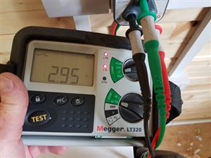
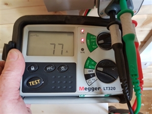
    Maximum earth fault loop impedance for a B32 MCB to disconnect in 0.4 second 1.37 ohms, maximum earth loop impedance for a 30 mA RCD 1666 ohms. 

    Time/current characteristic for B32 RCBP overcurrent characteristic current for time 0.1 sec to 5.0 second.

    So for the RCBO to trip due to a short circuit,  overload or an earth fault it needs to satisfy the requirements above. 
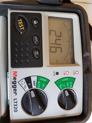
    19fb7d7db5e098de722d7020bdea1f36-huge-20190501_142123.jpg
    28eed91c6824c0d18ddfdae670b52694-huge-20190501_142338.jpg
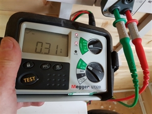
    649cd829e87b46465f15371214a6f68b-huge-20190501_142253.jpg
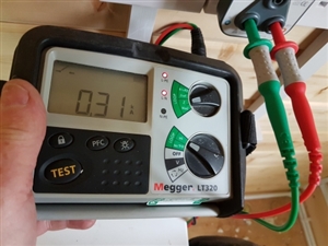
    a8e5ef1a6608dddce2e5c7775e0b2b7c-huge-20190501_142253.jpg

    So the RCBO relies on its RCD function to protect against earth faults and it's MCB function to protect against shorts and overload and all the requirements to allow it to function correctly seem to have been met.


    So why isn't the live neutral loop test satisfactory?


    Andy Betteridge
  • “Time/current characteristic for B32 RCBP overcurrent characteristic current for time 0.1 sec to 5.0 second.”


    That was supposed to read as: Time/current characteristic for B32 RCBO over-current characteristic current for time 0.1 sec to 5.0 second 160 amps.
  • 57be8f5d1f133c3d1d9dafa44c940f64-huge-20190501_142236.jpg

    And that was supposed to be the third photo.
  • The ADS aspect  of that socket is perfectly satisfactory, I would say the volt drop is not great though,  -  if you draw 13A through 0,75 ohms you  lose 17V, which you will notice, and is well outside the recommendations for a public supply.


    the 0.75 ohms and 300A PSSC are consistent with each other to  within rounding errors.
  • 147783e41f84131acf6d5148fa80db22-huge-20190501_142545.jpg


    It's a good job that the voltage is 16 volts above the 230 volts used for calculations to accommodate a potential 17 volts drop.

    From the intake there is around 127 metres of 25mm cables then 15 metres of 4 mm cables, overall it's a long circuit. 

    Based on those test results installing a C32/30mA RCBO that requires a loop impedance of 0.68 ohms and a current of 320 amps to operate correctly would seem to be completely unacceptable. 

    The RCBO could be reduced to a B20, but that would not really alter anything. 


    Andy
  • Given that the clause relating to L-E fauls is 


    411 .4.5 The following types of protective device may be used for fault protection:

    (i) An overcurrent protective device

    (ii) An RCD.

    Where an RCD is used for fault protection the circuit shall also incorporate an over current protective device in

    accordance with Chapter 43.


    That in turrn calls up 0.2 sec, 0.4 sec on TT / TN respectively for socket circutis, and 5 sec and 1 sec for distribution circuits, I think this is a case of (iii), so the RCD has to meet the times for shock protection, for faults to the CPC or an earthed part.

    so the MCB part only has to meet the much less onerous overcurrent requiermemnts


    433.1.1 The operating characteristics of a device protecting a conductor against overload shall satisfy the

    following conditions:

    (i) The rated current or current setting of the protective device (In) is not less than the design current (Ib) of the

    circuit, and

    (ii) the rated current or current setting of the protective device (In) does not exceed the lowest of the current carrying

    capacities (Iz) of any of the conductors of the circuit, and

    (iii) the current (h) causing effective operation of the protective device does not exceed 1.45 times the lowest of

    the current-carrying capacities (lz) of any of the conductors of the circuit

    For adjustable protective devices, the rated current (In) is the current setting selected.


    but that does not require disconnection in any particular time frame, except for the (very) general requirement


    430.3 General requirement

    A protective device shall be provided to break any overcurrent in the circuit conductors before such a current could

    cause a danger due to thermal or mechanical effects detrimental to insulation, connections, joints, terminations or

    the surroundings of the conductors.


    So the breaking time for L-N faults is set by cable damage considerations, which is adiabatic for high PSSC cases, but can be very slow if the PSSC is low enough- down to 'never' if the PSSC is less than the cable current rating - in those cases it is voltage drop that defines what is the limiting factor.


    So, on gensets and other sources of unknown supply impedance, likee caravan pitches, start with an RCD or earth fault relay, and all the other concerns vanish, except voltage drop.


  • What is the voltage drop during a dead short?


    Presumably that is the factor that needs consideration as it is what happens during a fault that matters rather than under normal usage when there is a load on the circuit.
  • when the fault comes on, the voltage drop will be 100% - there will be no L-N voltage at all at the fault point during a worst case fault.

    If the supply is a stiff (non collapsing source), but a long resistive distribution, then we can assume that the open circuit voltage divided by the loop resistance will set the current that flows. At the point of LN fault itself, the voltage to earth will be about 50% of the open circuit, as we expect equal voltage drop in L and N as , as we assume that all the volt drop is in the wires and they are equal sizes, so the voltage in the live will rise towards the origin, and the voltage in the neutral will fall towards earth.

    Of course,  this is not good for the wire, but not dangerous for an earthed person, because as soon as they touch the faulty part some current is diverted, L and N current is not equal, and  the RCD kicks in.


  • mapj1:

    . . . this is not good for the wire, but not dangerous for an earthed person, because as soon as they touch the faulty part some current is diverted, L and N current is not equal, and  the RCD kicks in. . .


    It may do. You are of course assuming that the supply at the location of the RCD is high enough for its internal electronics to be powered. I am of course assuming it has an internal voltage connection rather than taking its power from the measurement CT.


    Regards,


    Alan.