This discussion is locked.
You cannot post a reply to this discussion. If you have a question start a new discussion

LV 400V AC armoured cable glands are geeting overheat(Temp. measured more than 60 deg C)

Hello Electrical Team.

I would like to discuss an issue being facing in our Power plant(90MW). Our plant generation voltage is 11KV & Plant auxiliary & MCC voltage is 400V AC 50Hz. We have two sections of Power plant PP1 & PP2. In PP2 we are facing issue in LV MCC Panels. 

In LV system we have two BUS A & B. Both BUS's are getting power from their individual T/F(11KV/400V AC) & from here power is distributed to various MCC panels in plant. 

Booster no. 1 MCC have two LV breakers(Q1 & Q2) which are getting power from BUS A & B.

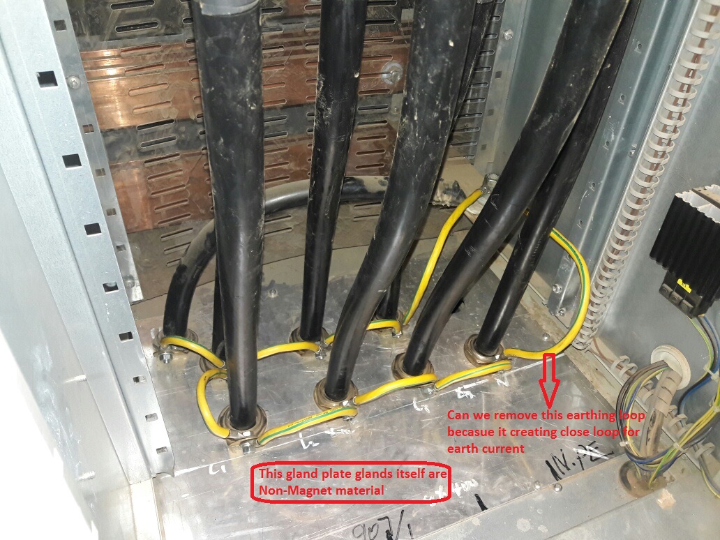
During last week we were found that Q1 breaker incoming cable insulation was melted around the cable gland area & checked the other glands also & they are also found overheated with abnormal temperature. then we took changeover to Q2 breaker but this is also now getting overheat. In main LV distribution panel side also cable glands are getting overheat which are connected to Q1 & Q2 breakers in MCC.

In one phase two cable are laid & connected, size is 400 sq.mm Armoured cable. R phase(L1 & L2), Y Phase(L1 &L2) & B Phase(L1 & L2). The current also not equal in two length of each phase.Pl see the below readings.
Line

Without Armoured

With Armoured

R Phase

L11

195 A

328A

115A

174A

L12

137 A

72A

Y Phase

L21

103A

332A

145A

306A

L22

167A

175A

B Phase

L31

150A

328A

120A

317A

L32

183A

199A


without armoured = Cable outside of MCC before entry in panel.

with armoured = After gland inside the panel. 

Team kindly go through the above said issue & your kind comments will be highly appreciated.
  • What is the construction of your cables? Are they SWA (Steel Wire Armour), AWA (Aluminium Wire Armour) or CWA (Copper Wire Armour). It is likely that you will need to re-terminate the cables with insulated glands on one end, usually the load end of the cable. 


    Regards,


    Alan.
  • If you cannot justify stopping to fix it until the next scheduled downtime, then  a proper version of that cooling fan may buy you some time.

    I'd be very worried by of any plan that involved taking the glands apart  with the power on.


    I do not think that looping a wire between the banjo washers on the glands will make any difference  - unless the gland plate is far too thin, and I'd expect 5mm thick as a minimum, or it will bend under the weight of the cables, the electrical cross-section of the gland plate should be  some hundreds of mm-sq equivalent , so adding some relatively thin wire in parallel to this will not help. Just take the banjo washers out altogether, and use them to make  key rings or something , for the potential fault currents these cables can supply they would be just fuses. Compare the strength to the lug on the true PE cable.

    (and if the gland plate is thin, how is any arc flash and blast contained, and what contains the cables against tonnes force of magneto-convulsion if there is ever a fault.)

    It is probably a bit late, but do you have access to the person who designed this, as all these things are normally calculated in at the beginning.


    Please use a small magnet to test what exactly is magnetic and what is not.
  • Hello Team,

    I was checked the gland plate & gland material with a piece of magnet & found that all material (Plates & Glands) are Non-Magnet. So now I'm bit confident that proper gland earthing will resolve our issue. 

    We have small doubt that gland earthing should close in loop or only from one side it should be earth after connecting each gland. Pl see the attached screen shot & share your comment. Only this is remaining now then will shift the load on this breaker & will observed the system.
  • I reckon that the heating effect is caused by induced currents in the electrically  conducting metal gland plate material, even if it is not ferrous, that causes I squared R heating due to the heavy currents. This would be avoided if all cables went through just one hole somehow, or the gland plate was non metallic, or clever slotting was created.


    Z.
  • A similar discussion from olden times.....

    https://www2.theiet.org/forums/forum/messageview.cfm?catid=205&threadid=47110


    Z.
  • This video clip claims to show induction heating of an aluminium container. This is the principle that I believe is involved with the heating of the gland plate, induced currents causing I squared R heating in the plate/glands. I presume that the heating element is made with a copper sheath to allow an A.C. magnetic field to invade the aluminium container, and the aluminium container is not just heated by radiated heat from the heating element.

    https://www.youtube.com/watch?v=PGXLTND9Dxk


    Z.
  • OK so glands and gland plates are not ferrous but there are large currents in the armouring.  Most likely cause of heating is the relatively poor connections made by the glands to the gland plate and the large currents flowing through them.

    You need to get to the bottom of what is causing these.    They could be diverted neutral currents or due to potential differences across the earthing network between the cable ends.  (I am assuming you have both ends of the cable armour earthed through the gland plates?)  This will involve a careful examination of the connections (N &E) between the two transformers and panels and the earthing arrangements on the site.


    You haven't explained what the earthing arrangements are at the panels in question but you may well have to isolate the armour at the remote end to fix this after of course making sure that there is a proper earth for that switchgear and circuits.  I don't know what the normal practice is where you are but in the UK such single point bonding of large cables is normal and results in greater current ratings.  Separate arrangements are made for the earthing.


    Hope this helps


  • Former Community Member
    0 Former Community Member
    How are the cables laid up on the containment ?


    Looking at the currents measured, there appears to gross variations in current share - suggest that all the cores of one phase run together, and so on - add to that badly fitted glands and inadequate earthing of those glands to a common gland plate and you could reasonably expect some pretty big circulating armour currents and those currents being particularly problematic at points of high resistance (such as between the gland and the armour)


    I may have missed it but the cable runs appear to be reasonably long  - so I suspect you are now at the point of deciding to accept the circulating currents (maybe not feasible considering the damage you are experiencing) or accepting that you need to change to insulating glands (or gland plate) at the load end, and accepting the potential risk of a standing voltage on the system with the attendant shock risk


    I suspect it was potentially badly designed, probably badly installed and has taken a few years for the heating effect to cause real problems - earthing the glands may help, but I would also check the gland is correct for the cable and is making sound contact with the armour. It's also possible that the gland plates are also getting pretty hot due to the circulating current flow and that is conducting heat into the gland, then into the armour and that local heating effect is rapidly deteriorating the cable bedding and insulation.


    You could also consider exposing the armour along the runs and adding a connection to the armour to effectively cross bond to adjacent armours (Raychem and similar sell heat shrink kits for this activity) - typically this would be done twice along the length of run


    Good luck


    OMS