This discussion has been locked.
You can no longer post new replies to this discussion. If you have a question you can start a new discussion

Wiring 10 vector heaters supplied by 10mm cable.

Former Community Member
Hi,


Whilst on site a few weeks ago, I noticed an electrician wired 10 vector heaters onto a 10 gangway switch.

​​​​each of the switches turned each of the heater's on. 

however, all these switches were supplied by the 10mm cable I was running above the ceiling tiles. 

Now I noticed each heater had a power rating of 2500 watts, 


So assuming all the heater's were turned on, and given the kind of premises it was, all the heater's would be on if used, that would have been a total of 25000 watts supplied by a 10mm cable. 


I'm just confused as to how he wired it,

Im pretty sure they were wired parralel, as each heater had it's own flex going straight to the switch board. Can anyone can help with a wiring diagram. It's really been bugging me.
Parents

  • they use to be on a ring final


    That makes it sound like the load isn't (too much) over 32A - or maybe they had problems and the 10mm² is an upgrade to something slightly larger.


    but a wiring diagram is what would stick in my head


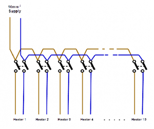
    Maybe this would be a start... in theory the basics are simple enough - one switch per heater all wired in parallel. (I've shown them as double pole, but single pole switches and a solid N connection might do if you didn't need N to be isolated.) So something like this:

    d15f963afe8231874d222bcd04eff91b-huge-basicswitches.png


    Obviously there'll be c.p.c.s in there as well, but I've omitted them for clarity (or due to laziness!)


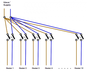
    There's an obvious problem with that layout though, as grid switch terminals won't accept anything as large as a 10mm² (let alone looped so two in a terminal) - so it would need modifying slightly - one way of doing that would be to terminate the 10mm² into a big terminal and take one wire from there to each switch.

    c23967d87f7518626b65b90c66f70f5d-huge-basicswitchesterminal.png


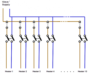
    Then there's likely the problem with fusing - as we're going from a large conductor (with presumably a large fuse) to smaller ones for each individual heater (and associated switch) - there's a real possibility that the protection for the 10mm² wouldn't provide protection for the smaller conductors. So ideally you'd have one fuse (or MCB) per heater and so your diagram would look something like this:

    8c70a0faef9e0101d504ab63a19e3a6b-huge-basicswitchesfused.png


    In fact, almost as if the top half were a distribution board (or consumer unit)...


    There are a lot of other possibilities, (in theory it is permitted to omit fault protection for short lengths of conductor under certain circumstances, which might allow for slightly different arrangements for example) - but hopefully that gives you an idea at least.


      - Andy.
Reply

  • they use to be on a ring final


    That makes it sound like the load isn't (too much) over 32A - or maybe they had problems and the 10mm² is an upgrade to something slightly larger.


    but a wiring diagram is what would stick in my head


    Maybe this would be a start... in theory the basics are simple enough - one switch per heater all wired in parallel. (I've shown them as double pole, but single pole switches and a solid N connection might do if you didn't need N to be isolated.) So something like this:

    d15f963afe8231874d222bcd04eff91b-huge-basicswitches.png


    Obviously there'll be c.p.c.s in there as well, but I've omitted them for clarity (or due to laziness!)


    There's an obvious problem with that layout though, as grid switch terminals won't accept anything as large as a 10mm² (let alone looped so two in a terminal) - so it would need modifying slightly - one way of doing that would be to terminate the 10mm² into a big terminal and take one wire from there to each switch.

    c23967d87f7518626b65b90c66f70f5d-huge-basicswitchesterminal.png


    Then there's likely the problem with fusing - as we're going from a large conductor (with presumably a large fuse) to smaller ones for each individual heater (and associated switch) - there's a real possibility that the protection for the 10mm² wouldn't provide protection for the smaller conductors. So ideally you'd have one fuse (or MCB) per heater and so your diagram would look something like this:

    8c70a0faef9e0101d504ab63a19e3a6b-huge-basicswitchesfused.png


    In fact, almost as if the top half were a distribution board (or consumer unit)...


    There are a lot of other possibilities, (in theory it is permitted to omit fault protection for short lengths of conductor under certain circumstances, which might allow for slightly different arrangements for example) - but hopefully that gives you an idea at least.


      - Andy.
Children
No Data