Hi,
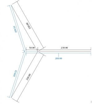
I have an application to control a bank of resistive heating elements (52Kw) in a Star configuration from a Eurotherm Power Management unit to control heat output.
Is it standard practice to connect the Neutral Point to Neutral ?
AJJewsbury:
Assuming the heating elements are resistive loads, there are three basic single-fault failure modes:
May I add a fourth - or a subdivision of (a) if you prefer - where several individual elements are connected in parallel on each phase. (probably not unlikely for a 52kW unit), If one element fails open circuit the current on that phase drops and the star point moves towards the other two phase (towards, the point where the elements on the other two phases would see 200V, but not quite), The remaining elements on the phase with the faulty element then see an increased voltage and start to overheat (with probably undesirable consequences). At least I think that was Geoff's example.
- Andy.

We're about to take you to the IET registration website. Don't worry though, you'll be sent straight back to the community after completing the registration.
Continue to the IET registration site