
Why is it forbidden to earth the neutral at the source of a 3 wire system?
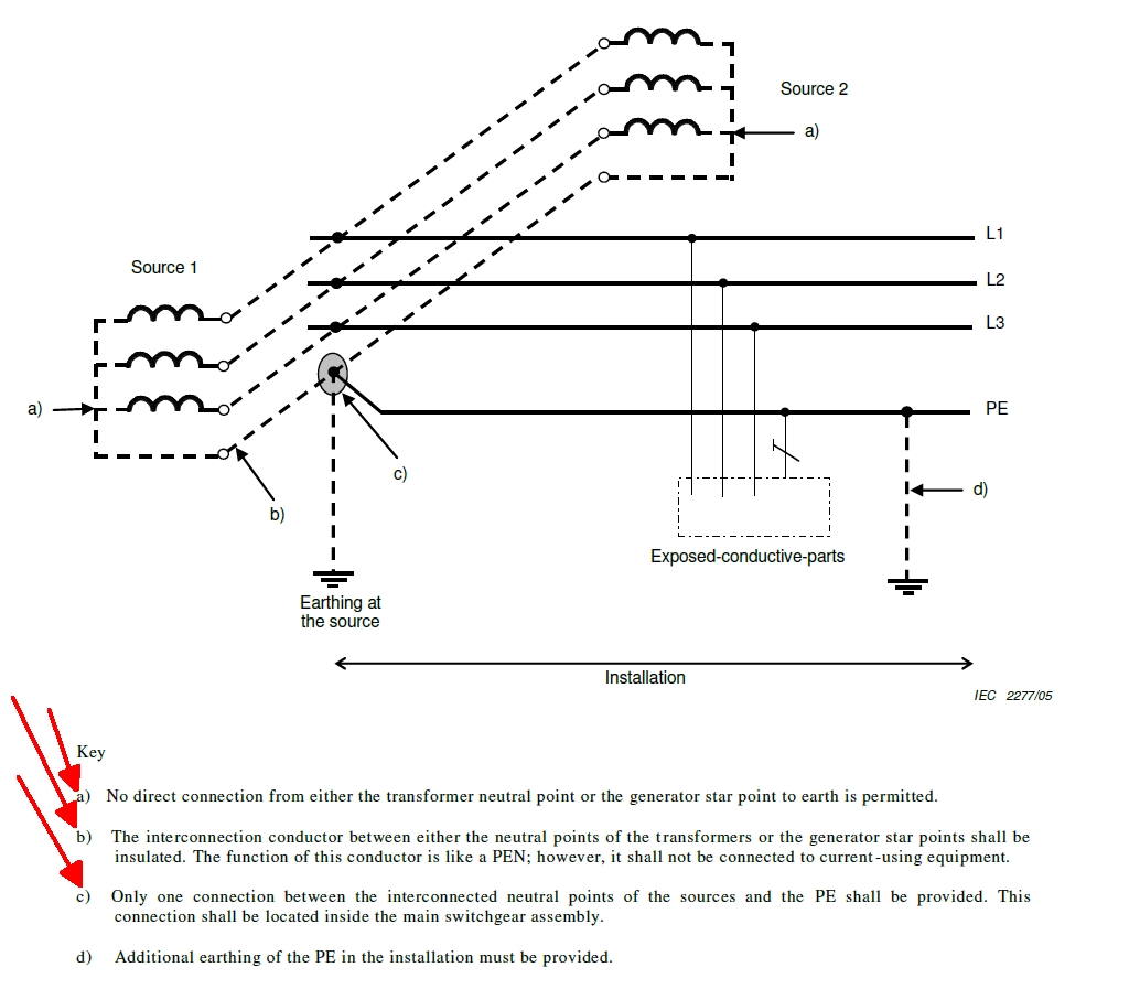
The diagram you linked to is specifically for multiple sources (nothing really to do with the number of wires - it's just an example - the preceding diagram in appendix 9 in BS 7671 shows the same arrangement for a 4-wire system) - it's just making the point that since you must have exactly one N-earth link in an entire TN-S system, that one link must be common to all the sources. You can't have each source having its own link otherwise you'd have multiple links and so N currents could flow through multiple paths (both N and PE) to each star point and you'd effectively end up with a TN-C-S system not a TN-S system.
You could have a N-PE link at just one of the sources and not at any of the others - but that can give problems if you ever need to take that particular source out of service for any reason (due to failure, maintenance or upgrade for example) especially if you need to keep the rest of the system running (a common reason for multiple sources is security of supply). Similarly you could have multiple links but switched via some controlling mechanism so that exactly one is closed at a time - but that can get complicated. Much simpler just to have one link, positioned after all the sources, but before any of the loads.
- Andy.
Much simpler just to have one link, positioned after all the sources, but before any of the loads.
Unless those sources are require an earth for safety reasons - such as at a substation with the transformer primary at HV - in such a case the secondary earthing link cannot safely be on the load side of any kind of switch, as if left to its own devices it may float up to some sort of mean of the primary voltage . This is more of a problem on single and split phase.
In such a case we quite often do really have 2 NE links, that may be in parallel, but arrange the path that may be shared to be short and fat enough that the full current of both sources could if need be be carried by any one link. Parallel transformer secondary windings are not that common but where it is needed, that is the easiest approach as the design of switched links requires serious thought about credible failure modes, and to be sure all of them are handled.

But how would current flow if there are no line to neutral connected loads?
We're about to take you to the IET registration website. Don't worry though, you'll be sent straight back to the community after completing the registration.
Continue to the IET registration site
