This discussion is locked.
You cannot post a reply to this discussion. If you have a question start a new discussion

Earthing neutral

Former Community Member
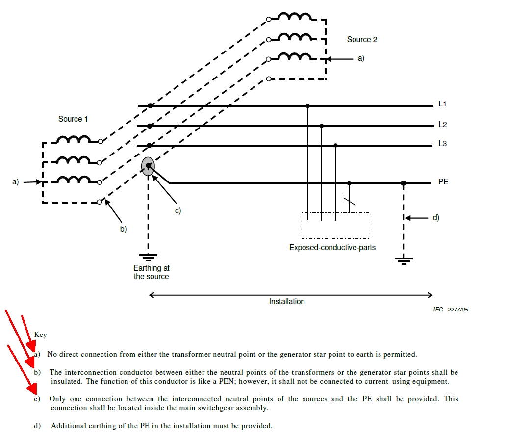
Why is it forbidden to earth the neutral at the source of a 3 wire system? 


  • Former Community Member
    0 Former Community Member
    Loads are phase-phase, transformers/gensets are star connected.


    I don't see the need to isolate the PE between the transformers and gear- I would earth them at both sources and the gear without hesitation.
  • But  isolation is very rarely fitted on a PE and that extract you posted does not mention it at all - actually switches and breakers are generally NOT permitted  in a PE, unless the phases are broken first ( same reason  the earth pin on a mains plug is longer than the other two. )

    Actually the whole diagram is a bit simplified, as we almost never parallel sources without some means of isolation, and gross over current protection,  to detect large fault currents - it is perhaps OK with 2 identical transformers on the same HV feed, but in many cases like genset and mains supplies you cannot even assume a particular phase relationship.


    When you say you would earth at TX and gear, are you meaning to terra-firma, as in an electrode into the ground at each location, or that you would connect to the HV earth ?

    This depends on the type of fault that is possible, and if you are considering an HV-LV fault, and the rise of earth voltage this causes. On a genset that is not credible, but  a mid winding to frame fault is.

  • Former Community Member
    0 Former Community Member
    I mean that the PE behind the switchgear is insulated and can not be earthed at either source.


    Yup- earthing the neutral by connecting it to an earthing electrode and also connecting it to the MV cable sheath.


  • Ah by your use of MV,  I think you are not from this continent - this may explain the mis-understandings.

    UK practice is not always to combine HV and LV earths - in the days when the rules were simpler, they were combined if the earth electrode impedance is less than 1 ohm, but had to have two electrodes kept well separated and the wiring insulated from each other if the ground conditions mean the electrode impedance too high, one for HV and the transformer case etc, and the LV one for the secondary side neutral. Nowadays the advice is a little changed, so it  requires you to look up the HV fault level, and then decide if the max credible HV fault current into the local earth would raise the local earth voltage to a dangerous level for a dangerous time (normally taken as 400v or so, but depends on the speed of the HV side ADS systems).  This is a bit more lenient than the old 1 ohm rules in some remote places where the HV lines are long, and more onerous to meet in places with more available fault current.

    The HV neutral is not distributed, so all our HV/LV transformers are delta on the HV input side and star on the LV output. This allows earth fault detection on the HV lines to be very fast and quite sensitive. (Imagine current transformers and breakers configured to work like an HV side RCD/GFCI )

    We also call the centre of a star transformer the neutral point, even if no load connects to it... this may not be helping the conversation.
  • Former Community Member
    0 Former Community Member
    But surely MV cables must have screens even if the load trafo is delta?
  • Former Community Member
    0 Former Community Member
    I up voted your reply btw :)


  • Ah, well in the built up areas the underground HV feeds will have an armour that is grounded - but further out the 11kV will be overhead and will normally be bare wires - we do not share HV and LV on the same poles, so bare HV is not as silly as it sounds. Some rural UK stuff to make it a bit clearer.

     typical 11kv overhead 3 phase 
    small 'pole -pig ' 11kV to 400V 3 phase+N


    The 3 white boxes on the pole are the outbound fuses for the LV phases. The thing at the top is a sort of open switch to perform 11kV isolation, and is operated by the long handle on the pole.


    In town the HV and the LV will be buried, so there is not so much to see.  Just   one of these  per 200 houses or so. The buried cables have earthed armour, and again the 'what  is the likely voltage kick?' question decides if HV and LV earths are separated or linked, bit now the armour resistance is in the equation.


  • Former Community Member
    0 Former Community Member
    Is the determining factor of HV-LV linking based on 1) the HV earth impedance 2) the operation time of the fuse/HV breaker?


  • Oh yes, like all UK ADS systems, the permissible exposed voltage and how long it may be exposed for are intimately linked, by the IEC shock curves, and an assumption that a healthy dry human is always more than 1000 ohms. ( link  to that curve)

    So the AC3 region upper boundary is the danger line. With a bit of a margin for safety we end up deciding that we can stand 50v for ages, 100V or so for 0.4 seconds, and 250V for about 0.2 seconds and anything much more than 500V needs to be disconnected very smartly indeed.

    That shape of that time kink is really down to the period of a human heartbeat - if you nudge the heart electrically for a very small fraction of the beat time, it takes more current to throw it off rhythm than a longer pulse duration - so the maximum safe exposure can be higher for short duration events. (and a really low current can pass forever and you scarcely feel  it)

    So the prospective fault current times the resistance to ground (by a combination of armour and electrodes if it is that sort of cable ) tells us the 'rise of earth potential' or ROERP that will occur. Breaker designs at the HV end tell us the breaking time = fault duration, and then someone paid to say so goes ho-hum and decides to bond or not.


    It was much simpler in the ' if it is 1 ohm treat as hot site, less then treat as cold ' days ! (that is 'hot' in the UK sense of being badly earthed, not in the USA sense of 'live'  though there is some overlap in what it may feel like, at least while a fault is on.)

  • Former Community Member
    0 Former Community Member
    In no disagreement here. Although sadly the US NEC does not have disconnection time requirments nor is there any concern given when the HV neutral is interconnected to the low voltage neutral.