This discussion is locked.
You cannot post a reply to this discussion. If you have a question start a new discussion

Ib or In for cable calculations

Hi all,


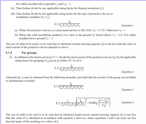
Got another one for you all, do you use Ib or In for cable calculations. I must admit that i have always used design current however after looking at recent threads on overload protection it appears i could be wrong. The way i read the attached extract is that, In should be used if there is potential for simulatenous overload, however Ib can be used if this is not the case. The immediate example that comes to mind are cleaners rings which are likely to never have over 2A connected load, however if we start putting the design current to 28A (OSG), they can only be grouped with 4 other cables before a 4mm is required. Do we not need to apply common sense to these calculations otherwise we will just get extremely oversized cables? 


The same goes for lighting circuits, if we know the connected load will be 2A , it seems counter-intuitive to put 6A as the design current, if alterations occur is it not up to the next designer to asses the situation before sticking new luminaires on the circuit?


Parents

  • broadgage:

    In my view, the design current should be the capacity of the circuit for socket outlet circuits. Future use is unknown and could include multiple electric heaters during central heating failure.

    A bit of wiggle room can be found in various ways, for domestic and similar sized installation with a single phase supply not exceeding 100 amps, remember that continuous full load operation of multiple 32 amp circuits simply can not happen. The cut out fuse would operate first.


    In the case of cleaners sockets, one work around is to reduce the number of circuits from say 4 ring finals to 2 ring finals. In such circumstances  I would consider more than 100 square meters of floor area per circuit to be acceptable. The circuit can still supply about half a dozen cleaning workers ALL using vacuum cleaners at the same time. Any unforeseen use of multiple electric heaters will trip the MCB rather than risk cable damage.

    2 ring finals/4 cables will reduce the derating if compared to 4 ring finals/8 cables.


    If say a dozen ring finals are needed, 10 for office IT equipment, and 2 for cleaners sockets, but with a modest total load, it might be worth limiting the total loading to 100 amps by a 100 amp fuse protecting the relevant sub main. The worst reasonably foreseeable loading might then be 6 cables, each loaded to 16 amps. Remember that with 3 ring finals fully loaded, that ALL the other cables downstream of the 100 amp fuse can be ignored for de-rating purposes as they cant be carrying more than 4 amps in total. Or since the loading might be spread unequaly between the legs of each ring final, perhaps allow for three cables loaded to 20 amps each, three more loaded to 12 amps each, and ignore all others.


    In the case of a lighting circuit, then IMHO a reasonable allowance for expansion should be allowed, perhaps the design load plus 50% would be reasonable.


    Broadgage, thankyou for the explanation, however if we take your scenario above with the IT equipment.


    There is a consumer unit serving the computer lab with 5 final ring circuits. 1 No. cleaners and 4 No. IT equipment (5 pcs and monitors per ring due to earth leakage). If we take the 4 rings in trunking liable to simultaneous overload only 3 are applicable to grouping as your example above. One leg of the ring can carry 20A worst case


    therefore 20/0.7 = 28.5A

    2.5mm twin is now not adequate.


    I guess the point I’m trying to get across is that in my opinion is not reasonable to allow for simultaneous overload in a large amount of cases otherwise we would have 4mm rings everywhere at is the norm to have 6+ circuits within dado trunking and the designer could simply not have allowed for simultaneous overload 


    I would be interested in hearing your thoughts 


Reply

  • broadgage:

    In my view, the design current should be the capacity of the circuit for socket outlet circuits. Future use is unknown and could include multiple electric heaters during central heating failure.

    A bit of wiggle room can be found in various ways, for domestic and similar sized installation with a single phase supply not exceeding 100 amps, remember that continuous full load operation of multiple 32 amp circuits simply can not happen. The cut out fuse would operate first.


    In the case of cleaners sockets, one work around is to reduce the number of circuits from say 4 ring finals to 2 ring finals. In such circumstances  I would consider more than 100 square meters of floor area per circuit to be acceptable. The circuit can still supply about half a dozen cleaning workers ALL using vacuum cleaners at the same time. Any unforeseen use of multiple electric heaters will trip the MCB rather than risk cable damage.

    2 ring finals/4 cables will reduce the derating if compared to 4 ring finals/8 cables.


    If say a dozen ring finals are needed, 10 for office IT equipment, and 2 for cleaners sockets, but with a modest total load, it might be worth limiting the total loading to 100 amps by a 100 amp fuse protecting the relevant sub main. The worst reasonably foreseeable loading might then be 6 cables, each loaded to 16 amps. Remember that with 3 ring finals fully loaded, that ALL the other cables downstream of the 100 amp fuse can be ignored for de-rating purposes as they cant be carrying more than 4 amps in total. Or since the loading might be spread unequaly between the legs of each ring final, perhaps allow for three cables loaded to 20 amps each, three more loaded to 12 amps each, and ignore all others.


    In the case of a lighting circuit, then IMHO a reasonable allowance for expansion should be allowed, perhaps the design load plus 50% would be reasonable.


    Broadgage, thankyou for the explanation, however if we take your scenario above with the IT equipment.


    There is a consumer unit serving the computer lab with 5 final ring circuits. 1 No. cleaners and 4 No. IT equipment (5 pcs and monitors per ring due to earth leakage). If we take the 4 rings in trunking liable to simultaneous overload only 3 are applicable to grouping as your example above. One leg of the ring can carry 20A worst case


    therefore 20/0.7 = 28.5A

    2.5mm twin is now not adequate.


    I guess the point I’m trying to get across is that in my opinion is not reasonable to allow for simultaneous overload in a large amount of cases otherwise we would have 4mm rings everywhere at is the norm to have 6+ circuits within dado trunking and the designer could simply not have allowed for simultaneous overload 


    I would be interested in hearing your thoughts 


Children
No Data