This discussion is locked.
You cannot post a reply to this discussion. If you have a question start a new discussion

Amtech Ring Circuit Grouping

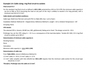
Firstly, Amtech recommends the design current of a ring circuit to be 20A as the attached image and it also the deafult, at first glance that appears correct as it assumed that no leg of the ring will carry more than 20A, however this doesn’t seem to make sense as when the design current is set at 32A Amtech calculates the Iz at 25A (20A/0.8) as the below table, so uses the 20A in this case, so I am not sure why 20A Design current is the default as this will be split between legs...


I have also been trying to establish how Amtech calculates the grouping factors of ring circuits (with no luck), I have been changing the design current to see if I could see a trend but there doesn’t seem to be one. I have attached the table below to see if anyone else has any ideas on the calculation, there doesn’t seem to be anything within the manual.


Design Current

Grouping Factor (2 circuits)

Iz

20

0.8

21

21

0.8

21.1

22

0.8

21.2

23

0.8

21.3

24

0.8

21.5

25

0.8

21.6

26

0.8

21.7

27

0.8

21.8

28

0.8

22

29

0.8

22.7

30

0.8

23.4

31

0.8

24.2

32

0.8

25


089fa81c383511347efc18dbb2a8d03c-huge-annotation-2019-10-17-113612.png

Parents
  • Former Community Member
    0 Former Community Member

    fiftyhertz:


    OMS:

    If you think about a ring circuit, if there is 20A in one leg, then there will only typically be 10A in the other leg (otherwise we'll be operating the CPD)


    I believe amtech uses standardised grouping factors for RFC's based on:


    1 ring - Factor 1.5

    2 Rings - Factor 1.19

    3 Rings - Factor 1.03

    4 Rings - Factor 0.94

    5 Rings - Factor 0.87

    6 Rings - Factor 0.82


    If we call the factor Cr then Itabulated > In x I/Cr (Amperes) and thus we need a cable rating of 21.33A for a single RFC (now BS 7671 mandates 20A and 2.5mm2 (which will carry 27A) - the 20A assumes the worst probable division of current around the ring. We tend to use the rating of the CPD rather than a RFC design current as it's quite probable the rings may well be subject to simultaneous overload (for design purposes)


    You may need other factors as usual for ambient temperature exceeding 30C and for cables in insulation


    Does that help


    Regards


    OMS


    OMS,


    I have saved that list down for future grouping as it very helpful. 


    In this case i dont think it fits as i am using Ib, and the correction factor is constant at 0.8. This can be seen from the last line of the table above. 32A design current @ 0.8 Cg. 20A/0.8 = 25A as calculated by Amtech.

    You can't use Ib as you have no real control over the usage - it could easily be fully loaded with adjacent fully loaded (or overloaded) circuits


    The bit i dont understand is as per the table, if the design current is 21A @ 0.8 Grouping (2 circuits), how the tabulated current Amtech spits out can be 21.1A.

    Because I'm using a design current of 32A and approximating a 0.66 and 0.33 split of current in the legs of the ring (21.3 A and 10.7A) - and thus one leg of the circuit is less than 33% loaded and can be effectively ignored for grouping purposes. What you should be seeing is that you can sensibly group 3 No fully loaded RFC's when using a 27A cable with no derating (ie Cr in each case is greater than 1) due to the headroom difference between 20A and 27A


    Hope this makes sense


    Regards


    OMS
Reply
  • Former Community Member
    0 Former Community Member

    fiftyhertz:


    OMS:

    If you think about a ring circuit, if there is 20A in one leg, then there will only typically be 10A in the other leg (otherwise we'll be operating the CPD)


    I believe amtech uses standardised grouping factors for RFC's based on:


    1 ring - Factor 1.5

    2 Rings - Factor 1.19

    3 Rings - Factor 1.03

    4 Rings - Factor 0.94

    5 Rings - Factor 0.87

    6 Rings - Factor 0.82


    If we call the factor Cr then Itabulated > In x I/Cr (Amperes) and thus we need a cable rating of 21.33A for a single RFC (now BS 7671 mandates 20A and 2.5mm2 (which will carry 27A) - the 20A assumes the worst probable division of current around the ring. We tend to use the rating of the CPD rather than a RFC design current as it's quite probable the rings may well be subject to simultaneous overload (for design purposes)


    You may need other factors as usual for ambient temperature exceeding 30C and for cables in insulation


    Does that help


    Regards


    OMS


    OMS,


    I have saved that list down for future grouping as it very helpful. 


    In this case i dont think it fits as i am using Ib, and the correction factor is constant at 0.8. This can be seen from the last line of the table above. 32A design current @ 0.8 Cg. 20A/0.8 = 25A as calculated by Amtech.

    You can't use Ib as you have no real control over the usage - it could easily be fully loaded with adjacent fully loaded (or overloaded) circuits


    The bit i dont understand is as per the table, if the design current is 21A @ 0.8 Grouping (2 circuits), how the tabulated current Amtech spits out can be 21.1A.

    Because I'm using a design current of 32A and approximating a 0.66 and 0.33 split of current in the legs of the ring (21.3 A and 10.7A) - and thus one leg of the circuit is less than 33% loaded and can be effectively ignored for grouping purposes. What you should be seeing is that you can sensibly group 3 No fully loaded RFC's when using a 27A cable with no derating (ie Cr in each case is greater than 1) due to the headroom difference between 20A and 27A


    Hope this makes sense


    Regards


    OMS
Children
No Data