This discussion is locked.
You cannot post a reply to this discussion. If you have a question start a new discussion

Unusual Earthing System

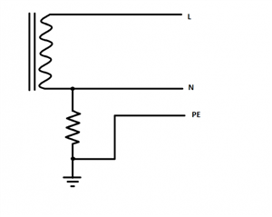
One of the Cahier Technique papers talked about an earthing system, which it described variously as cross between TT and TN-S or an 'impedance earthed TN-S' system, although I don't think either description is particularly accurate. Basically it suggests earthing the supply star point via an impedance, but then Earthing the consumer systems to the same electrode as the source:

66c3de7fa1842c6eefc0499bb3bad3a7-huge-notttnortn-s.png


As earth fault currents would be low, you'd need RCDs for ADS (just like a TT system), but the way the earthing is connected would seem to give a number of advantages over normal TT or TN systems. The most obvious perhaps is that exposed-conductive-parts remain at (or very close to) true Earth potential even during a L-PE fault - substantially reducing the risks of shock (even for the 5% of the population who aren't necessarily safe under normal ADS) - unlike a TN system where the point of the fault is likely to be at around half the line voltage, and in a TT system anything up to the full line voltage. It also less of an immediate issue if an RCD is a bit sticky or even fails to open altogether. They also claim less risk of damage or fire from L-PE faults than on TN systems - as the fault current is so much reduced.


So firstly what should this system be called? The impedance at the source is like an IT system - but the "T" would mean the consumer has their own earth electrode independent of the source's - which very specifically isn't the case here. Neither is the consumer's PE conductors directly connected to the system neutral which an "N" would usually indicate. As far as I know there isn't a letter to say the consumer's earth is connected directly to the supply's means of earthing (and not N) - maybe we could use "E" or "PE" for that - making it a IPE or IE system? I'm sure there are some better ideas out there.


My other thought was how would such an arrangement fair from the point of view of things like EMI or the effectiveness of SPDs - would it make any difference?


   - Andy.
Parents

  • OK, having Kirchoff's this idea on paper with some current flow in a consumer side fault to earth, I think I've convinced myself that an RCD would work, but I've still got a nagging thought I may have missed something.


    The loop impedance would probably be similar to that in a TT system - so the RCD should operate in the same manner. I'm not sure if some RCBOs with a FE connection might get upset if they see N drifting significantly away from PE, but that problem is probably manageable even if it does happen.


    During a fault in which one live of the 3 phases is earthed, this is what happens to the other wires. In effect the phase triangle of voltages stays the same size, or only flexes a bit, but you are now grounding the corner, rather than the star centre.


    Agreed. Could that effect be the cause of the problem mentioned in Z.'s video of motors being killed by an open circuit resistor? Would say 400V rather than 230V between conductor and frame be enough to over-strain insulation to breaking point? Or it it more likely to be due to something like capacitive coupling from the HV side of the transformer?


        - Andy.
Reply

  • OK, having Kirchoff's this idea on paper with some current flow in a consumer side fault to earth, I think I've convinced myself that an RCD would work, but I've still got a nagging thought I may have missed something.


    The loop impedance would probably be similar to that in a TT system - so the RCD should operate in the same manner. I'm not sure if some RCBOs with a FE connection might get upset if they see N drifting significantly away from PE, but that problem is probably manageable even if it does happen.


    During a fault in which one live of the 3 phases is earthed, this is what happens to the other wires. In effect the phase triangle of voltages stays the same size, or only flexes a bit, but you are now grounding the corner, rather than the star centre.


    Agreed. Could that effect be the cause of the problem mentioned in Z.'s video of motors being killed by an open circuit resistor? Would say 400V rather than 230V between conductor and frame be enough to over-strain insulation to breaking point? Or it it more likely to be due to something like capacitive coupling from the HV side of the transformer?


        - Andy.
Children
No Data